background image

MAINTENANCE

19

UP6RD–5–175, UP6RM–5–175, UP6RD–5–175

PERIOD

MAINTENANCE

Daily or Before Each
Operation

S

Check oil level. Fill as needed.

Operation

S

Drain receiver tank condensate. Open

the manual drain valve and collect and
dispose of condensate accordingly.

S

Test drain valve for proper operation.

Clean if needed

S

Check for unusual noise and vibration.

S

Ensure beltguards and covers are

securely in place.

S

Ensure area around compressor is free

from rags, tools, debris, and flammable or
explosive materials.

Weekly

S

Inspect air filter element(s). Clean or

replace if necessary.

Monthly

S

Inspect for air leaks. Squirt soapy water

around joints during compressor operation
and watch for bubbles.

S

Check tightness of screws and bolts.

Tighten as needed.

S

Clean drain valve

S

Clean exterior.

Each 2000 Hours /
1 year

S

Change synthetic oil while crankcase is

warm.

S

Replace filter element(s).

ROUTINE MAINTENANCE

This section refers to the various components which require

periodic maintenance and replacement.

The  SERVICE/MAINTENANCE CHART indicates the various

components’ descriptions and the intervals when maintenance has to
take place. Oil capacities, etc., can be found in the GENERAL
INFORMATION
 section of this manual.

Compressed air can be dangerous if incorrectly handled. Before

doing any work on the unit, ensure that all pressure is vented from the
system and that the machine cannot be started accidentally.

CAUTION

Before beginning any work on the compressor, open, lock and tag

the main electrical disconnect and close the isolation valve on the
compressor discharge. Vent pressure from the unit by slowly
unscrewing the coolant fill cap one turn. Unscrewing the fill cap opens
a vent hole, drilled in the cap, allowing pressure to release to
atmosphere. Do not remove the fill cap until all pressure has vented
from the unit. Also vent piping by slightly opening the drain valve. When
opening the drain valve or the coolant fill cap, stand clear of the valve
discharge and wear appropriate eye protection.

Compressed air can be dangerous if incorrectly handled. Before

doing any work on the unit, ensure that all pressure is vented from the
system and that the machine cannot be started accidentally.

Ensure that maintenance personnel are adequately trained,

competent and have read the Maintenance Manuals.

Prior to attempting any maintenance work, ensure that:–

.

all air pressure is fully discharged and isolated from the system. If

the automatic blowdown valve is used for this purpose, then allow
enough time for it to complete the operation.

.

the machine cannot be started accidentally or otherwise, by posting

warning signs and/or fitting appropriate anti–start devices.

.

all residual electrical power sources (mains and battery) are

isolated.

Prior to opening or removing panels or covers to work inside

a machine, ensure that:–

.

anyone entering the machine is aware of the reduced level of

protection and the additional hazards, including hot surfaces and
intermittently moving parts.

.

the machine cannot be started accidentally or otherwise, by posting

warning signs and/or fitting appropriate anti–start devices.

Prior to attempting any maintenance work on a running

machine, ensure that:–

.

the work carried out is limited to only those tasks which require the

machine to run.

.

the work carried out with safety protection devices disabled or

removed is limited to only those tasks which require the machine to be
running with safety protection devices disabled or removed.

.

all hazards present are known (e.g. pressurized components,

electrically live components, removed panels, covers and guards,
extreme temperatures, inflow and outflow of air, intermittently moving
parts, safety valve discharge etc.).

.

appropriate personal protective equipment is worn.

.

loose clothing, jewelry, long hair etc. is made safe.

.

warning signs indicating that Maintenance Work is in Progress are

posted in a position that can be clearly seen.

Upon completion of maintenance tasks and prior to returning

the machine into service, ensure that:–

.

the machine is suitably tested.

.

all guards and safety protection devices are refitted.

.

all panels are replaced, canopy and doors closed.

.

hazardous materials are effectively contained and disposed of.

WARNING

Do not under any circumstances open any drain valve or remove

components from the compressor without first ensuring that the
compressor is FULLY SHUT– DOWN, power isolated and all air
pressure relieved from the system.

Summary of Contents for UP6RD-5-175

Page 1: ...ATE APRIL 2003 UP6RD 5 175 UP6RM 5 175 UP6RX 5 175 ENCLOSED 60Hz OPERATION AND MAINTENANCE MANUAL This manual contains important safety information and must be made available to personnel who operate...

Page 2: ......

Page 3: ...IATIONS SYMBOLS Contact Ingersoll Rand for serial number Up to Serial No From Serial No Not illustrated Option NR Not required AR As required SM Sitemaster Sitepack HA High ambient machine WC Watercoo...

Page 4: ...ipment in which non approved repair parts are installed Standard warranty conditions may be affected Ingersoll Rand reserves the right to make changes and improvements to products without notice and w...

Page 5: ...rs which can result in serious injury Never operate the compressor near flammable liquids or vapors If used to spray flammable materials keep compressor at least 20ft away from the spray area HIGH PRE...

Page 6: ...CK OIL DECAL 5 32263832 1 ROTATING FAN DECAL 6 22075618 1 SHIPPING TAG 7 56276652 1 HOT SURFACE DECAL 8 1 MOTOR LABEL 9 30286686 1 ROTATION ARROW DECAL ON TOP OF MOTOR 10 1 PARTS LABEL 11 32341075 1 S...

Page 7: ...DECAL 6 22075618 1 SHIPPING TAG 7 56276652 1 HOT SURFACE DECAL 8 1 MOTOR LABEL 9 30286686 1 ROTATION ARROW DECAL ON TOP OF MOTOR 10 1 PARTS LABEL 11 32341075 1 SAFETY LABEL 12 54499306 1 IR LOGO 13 3...

Page 8: ...one common downstream plant effective isolation valves must be fitted and controlled by work procedures so that one machine cannot accidently be pressurized over pressurized by another Compressed air...

Page 9: ...SON SELECT can be fed directly into a drainage system that has downstream sewerage treatment As waste water regulations vary by country and region it is the responsibility of the user to establish the...

Page 10: ...ONLY WHEN SWITCH IS MOUNTED UNDER PRESSURE AND VOLTAGE FREE 5 THIS SCHEMATIC APPLIES TO UNITS USING A COMBINATION PRESSURE SWITCH Three Phase Wiring CONTROL PANEL OPTIONS COIL POWER SUPPLY OPTION 1 TO...

Page 11: ...GENERAL INFORMATION 9 UP6RD 5 175 UP6RM 5 175 UP6RD 5 175 Three phase combination pressure switch Mains Motor 2 Nm Tightening torque Single phase combination pressure switch Mains Motor...

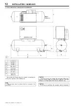
Page 12: ...INSTALLATION HANDLING 10 UP6RD 5 175 UP6RM 5 175 UP6RD 5 175 TYPICAL BASEPLATE MOUNTED COMPRESSOR mm Inches A 784 30 9 B 819 32 2 C 594 23 39 D E 335 13 19 F 614 24 2 G 12 0 472...

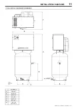
Page 13: ...TALLATION HANDLING 11 UP6RD 5 175 UP6RM 5 175 UP6RD 5 175 TYPICAL VERTICAL TANK MOUNTED COMPRESSOR mm Inches A 1769 69 7 B 813 32 01 C 404 15 91 D 649 25 6 E 404 15 91 F 678 26 7 G 14 2 x 22 0 56 x 0...

Page 14: ...is available for unloading and moving the compressor to the installation site NOTE Lifting equipment must be properly rated for the weight of the compressor CAUTION Lift the compressor by the shipping...

Page 15: ...nts DO NOT RUN THE COMPRESSOR WITHOUT REMOVING THE SHIPPING BLOCKS AND SHIPPING SCREWS A Shipping screws both ends 2 B Wooden shipping blocks 2 LOCATION IN THE PLANT WARNING FOR COMPRESSORS EQUIPPED W...

Page 16: ...ls not included in the list contact your dealer Materials Compatibility List Suitable VitonR TeflonR Epoxy Glass Filled Oil Resistant Alkyd Fluorosilicone Fluorocarbon Polysulfide 2 Component Urethane...

Page 17: ...165 150 40 NOTE If you use a petroleum based compressor lubricant at start up and decide to convert to ALL SEASON SELECT lubricant later the compressor valves must be thoroughly decarbonized and the...

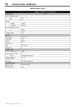
Page 18: ...ting temperature S _C 0 40 S _F 32 104 Compressor RPM 1475 MOTOR Nominal power 5HP 3 7kW Speed RPM 3450 Enclosure NEMA1 Insulation class F Amps See spec label Starts per hour 6 GENERAL DATA Oil Sump c...

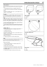
Page 19: ...e valve fully The air receiver will fill to cut out pressure and the motor will stop The unit is now ready for use NORMAL START UP 1 Set the pressure switch lever or control panel knob to OFF 2 Close...

Page 20: ...crewing the four screws holding the control panel The pressure switch cover can be removed by unscrewing the two screws holding the cover Pressure switch adjustment The compressor package will cut in...

Page 21: ...all pressure is vented from the system and that the machine cannot be started accidentally Ensure that maintenance personnel are adequately trained competent and have read the Maintenance Manuals Prio...

Page 22: ...d sheave are aligned and belt tension is satisfactory after installing new belts or tensioning existing belts FILTER REPLACEMENT 1 Unscrew and remove the wing nut securing the filter housing to its ba...

Page 23: ...d clean it Remove any debris that may be in the strainer body before replacing the filter screen 5 Replace plug and tighten with wrench 6 When putting the Electric Drain Valve back into service press...

Page 24: ...motor pulley crankshaft drive belt tension and alignment Repair or replace as required 2 Drain existing lubricant and refill with proper lubricant 3 Check line voltage and upgrade lines as required Co...

Page 25: ...er with 180 grit flex hone Knocking or rattling 1 Loose beltwheel or motor pulley excessive end play in motor shaft or loose drive belts 2 Compressor valves leaky broken carbonized or loose 3 Carbon b...

Page 26: ...or electric service panel too small 3 Poor contact on motor terminals or starter connections 4 Improper starter overload heaters 5 Bad motor 1 Check line voltage and upgrade lines as required Contact...

Reviews: