Operating Instructions
Operating & Maintenance Manual
Book: 22742944 (3-17-06) Rev. A
43
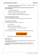
•
Verify that the piping from the orifice purge points to the exhaust system is not
clogged.
CAUTION
!
Blockage of the Y-strainers, orifices, or piping can result in flooding of
the vessels with condensate. If flooding occurs, excessive condensate
may enter the air stream and could result in damage to downstream
equipment.
Yearly Maintenance:
The normal maintenance interval on the primary and secondary IQ System filters is one year,
or earlier if pressure drop becomes excessive. Restriction indicators for the filters are mounted
on the filter support inside the front door, and will shut down the compressor if restriction
exceeds recommended values.
CAUTION
!
Excessively restricted filter elements may cause an increase in the
amount of aerosol water and oil carryover, which could result in damage
to downstream equipment. Normal service intervals should not be
exceeded.
Filter Replacement
•
With engine stopped, ensure pressure is relieved from air system.
•
Remove all wires and hoses connected to drains on bottom of each filter housing.
Inspect fittings and hoses for any blockage. Clean if necessary.
•
Using a chain wrench or similar tool, loosen the housing. The housing should be
removed by hand after loosening, taking care to prevent the housing from falling to
the floor panel.
•
Lower the housing to floor panel and lean it against the airend. Remove and replace
the filter element, being careful not to damage outer wrap.
Verify the part number of new element vs. old element, as the two IQ filters are of
different media.
•
Put a small amount of petroleum jelly or other non-synthetic grease on the element
O-Ring to aid installation into the filter head.
•
Replace housing making sure to not overtighten.
•
Repeat the above procedure on the remaining filter element.
•
Reconnect all wires and hoses to drains on bottom of each filter housing.
Summary of Contents for XHP1070WCAT
Page 6: ...6 Always use Ingersoll Rand Replacement parts ...
Page 7: ...Book 22742944 3 17 06 Rev A 7 Foreword ...
Page 12: ...12 Book 22742944 3 17 06 Rev A Always use Ingersoll Rand Replacement parts ...
Page 13: ...Book 22742944 3 17 06 Rev A 13 Safety ...
Page 21: ...Book 22742944 3 17 06 Rev A 21 Noise Emission ...
Page 27: ...Book 22742944 3 17 06 Rev A 27 General Data ...
Page 30: ...30 Always use Ingersoll Rand Replacement parts ...
Page 31: ...Book 22742944 3 17 06 Rev A 31 Operating Instructions ...
Page 45: ...45 Book 22742944 3 17 06 Rev A Always use Ingersoll Rand Replacement parts ...
Page 46: ...Operating Maintenance Manual Operating Instructions 46 Book 22742944 3 17 06 Rev A ...
Page 47: ...Book 22742944 3 17 06 Rev A 47 Maintenance ...
Page 60: ...60 Book 22742944 3 17 06 Rev A Always use Ingersoll Rand Replacement parts ...
Page 61: ...Book 22742944 3 17 06 Rev A 61 Lubrication ...
Page 65: ...Book 22742944 3 17 06 Rev A 65 Trouble Shooting ...
Page 75: ...75 Book 22742944 3 17 06 Rev A Always use Ingersoll Rand Replacement parts ...
Page 76: ...Operating Maintenance Manual Trouble Shooting 76 Book 22742944 3 17 06 Rev A ...
Page 77: ...Book 22742944 3 17 06 Rev A 77 Electrical ...
Page 82: ...82 Book 22742944 3 17 06 Rev A Always use Ingersoll Rand Replacement parts ...
Page 83: ...Book 22742944 3 17 06 Rev A 83 Electrical Schematics ...
Page 84: ...Operating Maintenance Manual Electrical Schematics 84 Book 22742944 3 17 06 Rev A ...
Page 85: ...Electrical Schematics Operating Maintenance Manual Book 22742944 3 17 06 Rev A 85 ...
Page 86: ...Operating Maintenance Manual Electrical Schematics 86 Book 22742944 3 17 06 Rev A ...
Page 87: ...Electrical Schematics Operating Maintenance Manual Book 22742944 3 17 06 Rev A 87 ...
Page 88: ...88 Book 22742944 3 17 06 Rev A ...
Page 90: ...Operating Maintenance Manual Electrical Schematics 90 Book 22742944 3 17 06 Rev A ...
Page 91: ... 2004 Ingersoll Rand Company Printed in the USA ...


