background image

Operating & Maintenance Manual

Maintenance

52

Book: 22742944 (3-17-06) Rev. A

warning signs indicating that Maintenance Work is in Progress are posted in a
position that can be clearly seen.

Upon completion of maintenance tasks and prior to returning the machine into 
service, ensure that:-

the machine is suitably tested.

all guards and safety protection devices are refitted.

all panels are replaced, canopy and doors closed.

hazardous materials are effectively contained and disposed of.

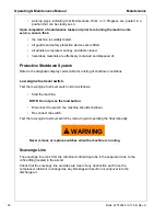
Protective Shutdown System

Refer to the diagnostic display codes table for a listing of shutdown conditions.

Low engine fuel level switch.

Test the low engine fuel level switch circuit as follows:

Start the machine.

NOTE: Do not press the load button.

Disconnect the switch, the machine should shutdown.

Re-connect the switch.

Test the low engine fuel level switch by removing and operating the float manually.

WARNING

!

Never remove or replace switches when the machine is running.

Scavenge Line

The scavenge line runs from the combined orifice/drop tube in the separator tank, to the 
orifice fitting located in the airend.

Check that the scavenge line and tube are clear of any obstruction each time the 
compressor lubricant is changed as any blockage will result in oil carryover into the 
discharge air.

Summary of Contents for XHP1070WCAT

Page 1: ...sonnel who operate and maintain this machine XHP1170WCAT Code A Revised 10 12 Doosan purchased Bobcat Company from Ingersoll Rand Company in 2007 Any reference to Ingersoll Rand Company or use of trademarks service marks logos or other proprietary identifying marks belonging to Ingersoll Rand Company in this manual is historical or nominative in nature and is not meant to suggest a current affilia...

Page 2: ...CALIFORNIA Proposition 65 Warning Diesel engine exhaust and some of its constituents are known to the State of California to cause cancer birth defects and other reproductive harm ...

Page 3: ...Schedule 24 A Compressed Air Leaks 24 B Safety and Control Systems 24 C Acoustic Materials 24 D Fasteners 25 E Enclosure Panels 25 F Air Intake and Engine Exhaust 25 G Cooling Systems 25 H Isolation Mounts 25 I Engine Operation 25 J Fuels and Lubricants 25 GENERAL DATA 27 OPERATING INSTRUCTIONS 31 Operating Controls and Instruments 32 Lifting Unit 34 Before Towing 34 Wagon Style Running Gear 34 Hi...

Page 4: ...tem 52 Low engine fuel level switch 52 Scavenge Line 52 Compressor Oil Filter 53 Removal 53 lnspection 53 Reassembly 54 Compressor Oil Separator Element 54 Removal 54 lnspection 54 Reassembly 55 Compressor Oil Cooler and Engine Radiator 55 Air Filter Elements 56 Removal 56 Reassembly 56 Ventilation 56 Cooling Fan Drive 56 Fuel System 57 Fuel Filter Water Separator 57 Charge Air Cooler Pipework 57 ...

Page 5: ...7 D Find and Correct Basic Cause 67 General Information 67 Wedge Diagnostic Display Codes 71 Trouble Shooting Chart 73 ELECTRICAL 77 General Information and Operational Theory 78 General 78 WEDGE Controller 78 Sensors and Transducers 79 Digital Inputs and Outputs 79 Controller Outputs 79 Pressure Control 79 Electronic Engine 80 Electrical System 80 Trouble Shooting Flow Chart 81 ELECTRICAL SCHEMAT...

Page 6: ...6 Always use Ingersoll Rand Replacement parts ...

Page 7: ...Book 22742944 3 17 06 Rev A 7 Foreword ...

Page 8: ...to European common market countries requires that the machine display the EC Mark and conform to various directives In such cases the design specification of this machine has been certified as complying with EC directives Any modification to any part is absolutely prohibited and would result in the CE certification and marking being rendered invalid A declaration of that conformity follows ...

Page 9: ...e that under our sole responsibility for manufacture and supply the product s NHP1500 XHP1070WCAT XHP1170WCAT HP1300WCU HP1600WCU XHP1070WCU XHP1170WCU 10 370 10 455 25 300 25 330 10 425 to which this declaration relates is are in conformity with the provisions of the above directives using the following principal standards EN29001 EN292 EN60204 1 EN1012 1 PN8NTC2 EN50081 EN50082 Issued at Mocksvi...

Page 10: ... of repair parts other than those included within the Ingersoll Rand approved parts list may create hazardous conditions over which Ingersoll Rand has no control Therefore Ingersoll Rand cannot be held responsible for equipment in which non approved repair parts are installed Ingersoll Rand reserves the right to make changes and improvements to products without notice and without incurring any obl...

Page 11: ...and maintenance requirements of the compressor During the preparation of this manual every effort was made to ensure the adequacy and accuracy of the contents Your Ingersoll Rand dealer will assist with setup and initial startup of the compressor He will also provide brief operating and service instructions and will insure that a copy of this manual is included with the machine Before starting the...

Page 12: ...12 Book 22742944 3 17 06 Rev A Always use Ingersoll Rand Replacement parts ...

Page 13: ...Book 22742944 3 17 06 Rev A 13 Safety ...

Page 14: ...hanical parts In particular safety related parts such as coupling hitch drawbar components road wheels and lifting bail should be checked for total security All components which are loose damaged or unserviceable must be rectified without delay Air discharged from this machine may contain carbon monoxide or other contaminants which will cause serious injury or death Do not breathe this air This ma...

Page 15: ...hich can result in serious injury or death Always carefully vent air supply line at tool or vent valve before performing any service The discharged air contains a very small percentage of compressor lubricating oil and care should be taken to ensure that downstream equipment is compatible If the discharged air is to be ultimately released into a confined space adequate ventilation must be provided...

Page 16: ...diesel fuel battery electrolyte WARNING Avoid ingestion skin contact and inhalation of fumes Should compressor lubricant come into contact with the eyes then irrigate with water for at least 5 minutes Should compressor lubricant come into contact with the skin then wash off immediately Consult a physician if large amounts of compressor lubricant are ingested Consult a physician if compressor lubri...

Page 17: ...G Do not attempt to slave start a frozen battery since this may cause it to explode Exercise extreme caution when using booster battery To jump battery connect ends of one booster cable to the positive terminal of each battery Connect one end of other cable to the negative terminal of the booster battery and other end to a ground connection away from dead battery to avoid a spark occurring near an...

Page 18: ...ne must be towed in a level attitude in order to maintain correct handling braking and lighting functions This can be achieved by correct selection and adjustment of the vehicle towing hitch and on variable height running gear adjustment of the drawbar 1 Make sure wheels tires and tow bar connectors are in safe operating condition and tow bar is properly connected before towing 2 When parking alwa...

Page 19: ... decal headings DANGER Red Background Indicates the presence of a hazard which WILL cause serious injury death or property damage if ignored WARNING Orange Background Indicates the presence of a hazard which CAN cause serious injury death or property damage if ignored CAUTION Yellow Background Indicates the presence of a hazard which WILL or can cause injury or property damage if ignored NOTICE Bl...

Page 20: ...ety Decals are available free of charge Safety decals are identified by the decal heading DANGER WARNING or CAUTION Decal part numbers are on the bottom of each decal and are also listed in the compressor s parts manual Submit orders for Safety Decals to the Mocksville Parts Service Department The no charge order should contain only Safety Decals Help promote product safety Replace decals that are...

Page 21: ...Book 22742944 3 17 06 Rev A 21 Noise Emission ...

Page 22: ...m or parts thereof b the air intake system or parts thereof c enclosure or parts thereof 2 Removal of any of the following a fan shroud b vibration mounts c sound absorption material 3 Operation of the compressor with any of the enclosure doors open Compressor Noise Emission Control Information A The removal or rendering inoperative other than for the purpose of maintenance repair or replacement o...

Page 23: ...ate purchaser and each subsequent purchaser that this air compressor was designed built and equipped to conform at the time of sale to the first retail purchaser with all applicable U S EPA Noise Control Regulations This warranty is not limited to any particular part component or system of the air compressor Defects in the design assembly or in any part component or system of the compressor which ...

Page 24: ... shut down immediately and correct the leak s B Safety and Control Systems Repair or replace all safety and control systems or circuits as malfunction occurs No compressor should be operated with either system bypassed disabled or nonfunctional C Acoustic Materials In daily inspections observe these materials Maintain all acoustic material as nearly as possible in its original condition Repair or ...

Page 25: ... systems should be inspected after each 100 hours of operation for loose damaged or deteriorated components Repairs or replacements should be made before the next period of use G Cooling Systems All components of the cooling system for engine water and compressor oil should be inspected every 250 hours of use Any discrepancies found should be corrected before placing the unit back in operation Unr...

Page 26: ...Manual Noise Emission 26 Book 22742944 3 17 06 Rev A MAINTENANCE RECORD FOR NOISE EMISSION CONTROL AND EXTENDED WARRANTY ITEM NO DESCRIPTION OF WORK HOURMETER READING MAINT INSPECT DATE LOCATION CITY STATE WORK DONE BY NAME ...

Page 27: ...Book 22742944 3 17 06 Rev A 27 General Data ...

Page 28: ...System 24VDC 24VDC Full Load Speed rpm 1800 1800 No Load Speed rpm 1350 1350 FLUID CAPACITIES U S Gallons litres Compressor Lubricant 55 208 55 208 Engine Lube including filter 10 5 40 10 5 40 Engine Coolant radiator 15 2 57 5 15 2 57 5 Fuel Tank Clean DIESEL fuel 230 870 230 870 UNITS MEASUREMENTS WEIGHTS Feet Meters HSRG WAGON RG LRG Overall Length 24 3 7 4 19 2 5 85 19 2 5 85 Overall Height 8 3...

Page 29: ... 36864379 Filter Inlet Secondary Engine AE inlet 2 35362235 Filter Oil Engine C15 1 55362268 Filter Coolant Engine C15 1 22730014 Filter Fuel Eng primary w seals C15 1 22090526 Filter Fuel Engine secondary C15 1 22730022 Filter Bowl Fuel primary C15 1 CAUTION Any departure from the specifications may make this equipment unsafe RUNNING GEAR Tire Size 215 75R17 5H 215 75R17 5H NA Towing Speed maximu...

Page 30: ...30 Always use Ingersoll Rand Replacement parts ...

Page 31: ...Book 22742944 3 17 06 Rev A 31 Operating Instructions ...

Page 32: ...rol panel Controlled by Switch 14 2 High Compressor Temp Fault indicator lamp Indicates shutdown due to high compressor temperature 3 Low Radiator Coolant Level Alarm indicator lamp Indicates engine coolant needs service 4 Low Engine Oil Pressure Fault indicator lamp Indicates shutdown due to low engine oil pressure 5 Restricted Air Filter Alarm indicator lamp Indicates engine compressor air inlet...

Page 33: ...or list of codes and service requirements 13 Ether Inject Injects a measured shot of ether for aid in cold weather starting of engine CAUTION Use Sparingly 14 Panel Light Switch Controls panel lamp 1 15 Pressure Control Momentary contact switch Allows engine to warm up at low compressor pressure 16 Main Power Control Switch ON OFF Start Switch 17 Heaters ON OFF Power Switch for regulation and IQ h...

Page 34: ... jack to raise or lower lunette eye Use tow vehicle whose towing capacity is greater than the gross weight of this unit see general data Do not tow this unit in excess of 65 mph Place wheel chocks under tires before disconnecting from towing vehicle When raising or lowering lunette eye always stand to one side Wheel Chock HSRG Located inside of front towbar Secure unit with chocks before disconnec...

Page 35: ...y description or any other source of compressed air without first making sure a check valve is used between the header and the unit If this unit is connected in parallel with another unit of higher discharge pressure and capacity a safety hazard could occur in a back flow condition WARNING Unrestricted air flow from a hose will result in a whipping motion of the hose which can cause serious injury...

Page 36: ...ired Do not overfill To jump start connect the positive booster charger cable to the 24VDC positive terminal of the battery Then connect the negative booster charger cable to the engine block Not to the negative terminal of the weak battery After starting disconnect the negative cable from engine block then from the booster battery charger Disconnect positive cable from both batteries WARNING Do n...

Page 37: ...om the engine Refer to the Engine Operator s Section for fuel specifications NOTICE To minimize condensation water in the fuel tank it is recommended to fill the tank at the end of each day NOTE This machine will not allow engine starting if the fuel level is below the minimum fuel shut off level WARNING This machine produces loud noise with doors open Extended exposure to loud noise can cause hea...

Page 38: ...t these temperatures 3 When the keyswitch is turned to START the engine starter will be engaged Do not operate the engine starter motor for more than ten 10 seconds without allowing at least one minute cooling time between start attempts Extended engine starter engagement will result in starter drop out and generate a starter engagement time fault CAUTION Ether is an extremely volatile high flamma...

Page 39: ...h the required volume flow Operation Loaded Assume engine has been started and is running in the unload state at 1200 RPM If there is air demand pressure falls below the load point pressure compressor will load at 1200 RPM by opening the inlet valve As air demand rises and falls engine speed is controlled between 1200 RPM and 1800 RPM to match the required flow while maintaining rated pressure Ope...

Page 40: ...h provides cooler cleaner air than from a standard portable compressor The system utilizes an integral aftercooler high efficiency filtration and a patented condensate disposal system to provide the cool clean air The condensate disposal system injects all liquid condensed from the moisture separator and filters into the engine exhaust system where it is vaporized by heat This eliminates the need ...

Page 41: ...d air and condensate water with a small amount of compressor lubricant exits the aftercooler and enters the moisture separator where most of the condensate is removed The compressed air then flows through two stages of filtration where the aerosol water and oil is removed down to approximately 0 01 ppm and all particulates are removed down to 0 01 micron At the bottom of the moisture separator and...

Page 42: ... the event that the unit is operating under abnormal conditions i e an enclosure door open which would cause excessive cooling of the aftercooler a temperature sensor in the aftercooler outlet header will signal the TCU to further close the louvers if the compressed air temperature falls to approximately 36º F or lower There are no user selectable or serviceable components in the TCU Contact Inger...

Page 43: ...h could result in damage to downstream equipment Normal service intervals should not be exceeded Filter Replacement With engine stopped ensure pressure is relieved from air system Remove all wires and hoses connected to drains on bottom of each filter housing Inspect fittings and hoses for any blockage Clean if necessary Using a chain wrench or similar tool loosen the housing The housing should be...

Page 44: ...ral times to assure that linkage is not binding 4 With air cylinder rod L fully extended take slack out of spring G by moving nuts E and F Tighten nuts 5 Start unit and allow to warm up for 3 to 5 minutes 6 Push Service Air button on control panel 7 With service air valve closed adjust pressure regulator PR to rated pressure 350 psi plus 10 psi 70 kPa as follows 8 Loosen locknut M counterclockwise...

Page 45: ...45 Book 22742944 3 17 06 Rev A Always use Ingersoll Rand Replacement parts ...

Page 46: ...Operating Maintenance Manual Operating Instructions 46 Book 22742944 3 17 06 Rev A ...

Page 47: ...Book 22742944 3 17 06 Rev A 47 Maintenance ...

Page 48: ...C Air Cleaner Precleaner Dumps C Fan Alternator Belts C Battery Connections Electrolyte C Tire Pressure and Surface C Wheel Lug Nuts C Hoses Oil Air Intake etc C Automatic Shutdown System C Air Cleaner System C Compressor Oil Cooler Exterior C Engine Rad Oil Cooler Exterior C Fasteners Guards C Air Cleaner Elements R WI Disregard if not appropriate for this particular machine D Drain 1 or 3000 mil...

Page 49: ...T Scavenger Orifice Related Parts C Oil Separator Element R Feed Pump Strainer Cleaning C Valve Clearance Check C Lights running brake turn CBT Pintle Eye Bolts CBT Brakes C C Brake linkage C Emergency stop T Running gear linkage G Safety valve C Running gear bolts 1 C Disregard if not appropriate for this particular machine D Drain 1 or 3000 miles 5000km whichever is the sooner G Grease 2 or as d...

Page 50: ...automatic blowdown fails to operate then pressure must be gradually relieved by operating the manual blowdown valve Suitable personal protective equipment should be worn Ensure that maintenance personnel are adequately trained competent and have read the Maintenance Manuals Initial 500miles 850 km Daily Weekly Monthly 3 Months 500 hrs 6 Months 1000 hrs 12 Months 2000 hrs Scavenge line C Engine bre...

Page 51: ... devices Disconnect battery cables Prior to opening or removing panels or covers to work inside a machine ensure that anyone entering the machine is aware of the reduced level of protection and the additional hazards including hot surfaces and intermittently moving parts The machine cannot be started Prior to attempting any maintenance work on a running machine ensure that the work carried out is ...

Page 52: ...ay codes table for a listing of shutdown conditions Low engine fuel level switch Test the low engine fuel level switch circuit as follows Start the machine NOTE Do not press the load button Disconnect the switch the machine should shutdown Re connect the switch Test the low engine fuel level switch by removing and operating the float manually WARNING Never remove or replace switches when the machi...

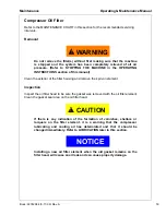
Page 53: ...the exterior of the filter housing and remove the spin on element lnspection Inspect the oil filter head to be sure the gasket was removed with the oil filter element Clean the gasket seal area on the oil filter head CAUTION If there is any indication of the formation of varnishes shellacs or lacquers on the filter element it is a warning that the compressor lubricating and cooling oil has deterio...

Page 54: ...r Element Refer to the MAINTENANCE CHART in this section for the recommended servicing intervals If however the element has to be replaced then proceed as follows Removal WARNING Do not remove the filter s without first making sure that the machine is stopped and the system has been completely relieved of all air pressure Refer to STOPPING THE MACHINE in the OPERATING INSTRUCTIONS section of this ...

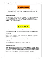
Page 55: ...this manual and check for leakage before the machine is put back into service Compressor Oil Cooler and Engine Radiator When grease oil and dirt accumulate on the exterior surfaces of the oil cooler and radiator the efficiency is impaired It is recommended that each month the oil cooler and radiator be cleaned by directing a jet of compressed air carrying if possible a non flammable cleaning solve...

Page 56: ... element s when the machine is running Clean the exterior of the filter housing and remove the filter element by releasing the nut Reassembly Assemble the new element into the filter housing ensuring that the seal seats properly Secure element by tightening nut Before restarting the machine check that all clamps are tight Ventilation Always check that the air inlets and outlets are clear of debris...

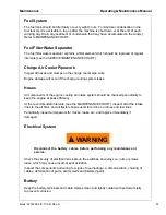
Page 57: ...es All components of the engine cooling air intake system should be checked periodically to keep the engine at peak efficiency At the recommended intervals see the MAINTENANCE CHART inspect all of the intake lines to the air filter and all flexible hoses used for air lines oil lines and fuel lines Periodically inspect all pipework for cracks leaks etc and replace immediately if damaged Electrical ...

Page 58: ...0 miles 30 kilometres after refitting the wheels Refer to the TORQUE SETTING TABLE later in this section Lifting jacks should only be used under the axle The bolts securing the running gear to the chassis should be checked periodically for tightness refer to the MAINTENANCE CHART for frequency and re tighten where necessary Refer to the TORQUE SETTING TABLE later in this section Lubrication CAUTIO...

Page 59: ... to STOPPING THE MACHINE in the OPERATING INSTRUCTIONS section of this manual Completely drain the receiver separator system including the piping and oil cooler by removing the drain plug s and collecting the used oil in a suitable container Replace the drain plug s ensuring that each one is secure NOTE If the oil is drained immediately after the machine has been running then most of the sediment ...

Page 60: ...60 Book 22742944 3 17 06 Rev A Always use Ingersoll Rand Replacement parts ...

Page 61: ...Book 22742944 3 17 06 Rev A 61 Lubrication ...

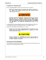
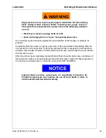
Page 62: ...r are in Maintenance Section All filters and filter elements for air and compressor lubricant must be obtained through Ingersoll Rand to assure the proper size and filtration for the compressor Compressor Oil Change These units are normally furnished with an initial supply of oil sufficient to allow operation of the unit for approximately 6 months or 1000 hours whichever comes first If a unit has ...

Page 63: ...voir piping and cooler If the oil is drained immediately after the unit has been run for some time most of the sediment will be in suspension and therefore will drain more readily However the fluid will be hot and care must be taken to avoid contact with the skin or eyes After the unit has been completely drained of all old fluid close the drain valve install new oil filter elements Add oil in the...

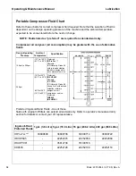
Page 64: ...Refer to operator s manual warranty section for details or contact your I R representative DesignOperating Pressure Ambient Temperature Specification 100 psi to 300 psi 10 F to 125 F 23 C to 52 C Preferred IR Pro Tec Alternate ISO Viscosity Grade 46 with rust and oxidation inhibitors designed for air compressor service 350 psi 10 Fto125 F 23 C to 52 C 65 Fto125 F 18 C to 52 C Preferred IR XHP 605 ...

Page 65: ...Book 22742944 3 17 06 Rev A 65 Trouble Shooting ...

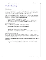
Page 66: ...Follow down that column to find the potential cause or causes The causes are listed in order 1 2 3 etc to suggest an order to follow in trouble shooting A Think Before Acting Study the problem thoroughly and ask yourself these questions 1 What were the warning signals that preceded the trouble 2 Has a similar trouble occurred before 3 What previous maintenance work has been done 4 If the compresso...

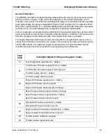
Page 67: ...e engine diagnostic fault codes can also be read with the manufacturer s service tool A service tool connector is mounted on the engine This connector provides a connection to the J1939 CAN network For advanced engine troubleshooting it is recommended that the manufacturer s service tools be used with accompanying service literature Fault Code Caterpillar Model C15 Engine Diagnotic Codes 13 Fuel T...

Page 68: ...tor Actuation Pressure System Fault 42 Engine Timing Calibration Required 46 Low Engine Oil Pressure Warning Low Engine Oil Pressure Derate Low Engine Oil Pressure Shutdown 49 Air Inlet Heater Relay Open Current Below Normal Air Inleter Heater Relay Grounded Current Above Normal 51 System Voltage Intermittent Erratic High Low 56 Check Programmable Parameters 58 J1939 Data Link Communication 61 Hig...

Page 69: ...rature Shutdown 65 High Fuel Temperature Warning High Fuel Temperture Derate High Fuel Temperature Shutdown 71 Injector Cylinder 1 Fault 72 Injector Cylinder 2 Fault 73 Injector Cylinder 3 Fault 74 Injector Cylinder 4 Fault 75 Injector Cylinder 5 Fault 76 Injector Cylinder 6 Fault Fault Code Caterpillar Model C15 Engine Diagnotic Codes ...

Page 70: ...ngine shuts itself down reason unknown 29 CPRSR Malf 0 Low AE Oil Pressure 31 CPRSR Malf 20 Disch Temp RT2 Sensor Fault 32 CPRSR Malf 10 Sep Tank Pressure PT1 Sensor Fault 33 CPRSR Malf Sep Tank Press 20 psi during start attempt engine will not crank 34 CPRSR Malf 0 Machine Over Pressure 35 CPRSR Malf 1 Safety Valve Open 36 CPRSR Malf 2 Sep Tank Temp 247 F 50 CPRSR Malf 3 Machine ID not valid 51 C...

Page 71: ...dule Failure no comm for 17 sec 73 CPRSR Malf Low Fuel Level fuel level fuel level 3 Air Filter Restriction soiled filter Low Battery Voltage battery charging cond Low Engine Oil Pressure low engine oil press Low Coolant Level engine coolant level High Engine Coolant Temp high engine temp high engine temp 10 IQ Filter Restriction IQ filter restriction 3 High Disch Temp RT2 247 F high comp temp 3 A...

Page 72: ...un Low Battery Voltage Check electrolyte level Check connections Blown Fuse Replace fuse Malfunctioning Start Switch Replace switch Clogged Fuel Filters Service filters See Engine Operator s Manual Out of Fuel Add CLEAN fuel Compressor Oil Temp too High See Complaint 6 Engine Water Temp too High Check fluid level If necessary Add Engine Oil Pressure too Low See Complaint 3 and Complaint 4 Loose Wi...

Page 73: ... Oil Check spec in this manual Dirty Cooler Clean exterior surfaces Dirty Operating Conditions Move unit to cleaner environment Clogged Oil Filter Elements Replace elements Change oil Loose or Broken Belts Tighten or replace belt set Operating Pressure too High Reduce pressure to spec Recirculation of Cooling Air Close side doors Replace belly pan Malfunctioning Thermostat Replace thermostat in by...

Page 74: ... Install correct element 10 Short Air Cleaner Life Dirty Operating Conditions Move unit to cleaner environment Inadequate Element Cleaning Install new element Incorrect Stopping Procedure Read procedure in this manual Wrong Air Filter Element Install proper element 11 Will Not Unload Malfunctioning Inlet Butterfly Valve Inspect valve fit Re adjust per Section 6 Ice in Regulation Lines Orifice Appl...

Page 75: ...75 Book 22742944 3 17 06 Rev A Always use Ingersoll Rand Replacement parts ...

Page 76: ...Operating Maintenance Manual Trouble Shooting 76 Book 22742944 3 17 06 Rev A ...

Page 77: ...Book 22742944 3 17 06 Rev A 77 Electrical ...

Page 78: ...r 10 size nuts The first function of the WEDGE is to scan all analog and digital inputs at a fixed interval These inputs are scanned every 50 milliseconds The analog values are then compared against minimum and maximum values and an ALERT or SHUTDOWN is issued if a value is out of range The various ALERTS and SHUTDOWNS are listed in section The second function of the WEDGE controller is machine di...

Page 79: ...start switch air filter switches and IQ filter switches The WEDGE controller provides 24V DC digital outputs to control solenoids start compressor and DC heaters These are 24V DC ON and 0V DC OFF They are current limited and short circuit protected Controller Outputs The WEDGE controller has three different types of outputs frequency pulse width modulated PWM and 24V DC digital ON OFF The frequenc...

Page 80: ... the cable is connected to the machine metal at the WEDGE controller end The connection must be properly made with good metal to metal contact between the wire terminal and the machine metal The engine diagnostics connector is located on the left side of the engine This is used to connect the engine manufacturers service tools to the CAN network This connector also provides 24V DC power to these s...

Page 81: ...Electrical Operating Maintenance Manual Book 22742944 3 17 06 Rev A 81 Trouble Shooting Flow Chart ...

Page 82: ...82 Book 22742944 3 17 06 Rev A Always use Ingersoll Rand Replacement parts ...

Page 83: ...Book 22742944 3 17 06 Rev A 83 Electrical Schematics ...

Page 84: ...Operating Maintenance Manual Electrical Schematics 84 Book 22742944 3 17 06 Rev A ...

Page 85: ...Electrical Schematics Operating Maintenance Manual Book 22742944 3 17 06 Rev A 85 ...

Page 86: ...Operating Maintenance Manual Electrical Schematics 86 Book 22742944 3 17 06 Rev A ...

Page 87: ...Electrical Schematics Operating Maintenance Manual Book 22742944 3 17 06 Rev A 87 ...

Page 88: ...88 Book 22742944 3 17 06 Rev A ...

Page 89: ...Electrical Schematics Operating Maintenance Manual Book 22742944 3 17 06 Rev A 89 CPN 22840775 ...

Page 90: ...Operating Maintenance Manual Electrical Schematics 90 Book 22742944 3 17 06 Rev A ...

Page 91: ... 2004 Ingersoll Rand Company Printed in the USA ...

Reviews: