background image

21

 ASSEMBLY OF THE IR90VR SERIES PAVING BREAKERS 

 GENERAL INSTRUCTIONS 

Do not repair the tool at the work site. Always take the 
tool to a repair shop. Never drag the tool on the ground. 
The air port and other openings will become clogged 
with dirt and debris.

Before assembly of the breaker, clean all parts thor-
oughly and lubricate surfaces with a thin film of recom-
mended oil (see Lubrication).

Apply a film of O-ring lubricant to all O-rings before 
final assembly.

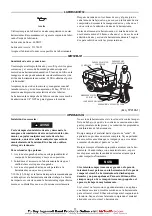
It is recommended that the assembling of the nozzle (2) 
should be carried out by the manufacturer or authorised 
distributor.

The existence of a piston air cushion should be deter-
mined. Hold the cylinder vertically and allow the piston 
to drop down the bore small diameter first. An air cush-
ion is present if the piston “bounces” at the bottom of 
the cylinder and no metal to metal contact noise can be 
heard. If a cushion is not present contact your authorised 
Ingersoll-Rand repair center for advice.

 CYLINDER ASSEMBLY 

Grip the cylinder (1) vertically in a vice protected with 
leather or copper covered vice jaws.
Lubricate and insert the piston (4) small end first into the
bore. Check for cushion.
Lubricate and slide the valve ring (34) onto the cylinder (1) 
and replace valve cover (31).
Position the valve spacer (30) on top of the valve cover (31).
Replace the sealing ring (28).

 HANDLE ASSEMBLY 

If the handle stop (14) was removed during disassembly it
should be replaced with a new part as the retaining feature
is severed on removal. Locate the stop in the hole in the han-
dle and tap sharply into place using a soft drift and hammer.
If the hand grip rubbers (10) have been removed these 
should now be replaced. Lubricate the inside of the rubber 
with soapy water and slide the new rubber into position.
Assemble left and right hand, hand grips (8 and 9), trigger
(7) together with sleeve (13), lubricate around the pivot area
and position the sub assembly along the slot in handle body
(5).

Note:

It is usual to position the trigger lever on the same 
side as the air inlet of the handle body.

Locate the handle springs (11) between hand grips and han-
dle body and fix the assembly in place by drifting or pressing
in handle pivot pin (12).
Lubricate the trigger pin (15), trigger ball (16) and replace
in the air inlet connection of the handle body.

Note:

The trigger pin has a reduced diameter which is 
placed next to the trigger ball.

Locate the trigger spring (17) on top of the trigger ball. 
Apply thread retainer (loctite 243, or similar) on the thread 
of the inlet bushing (18) and tighten to 147 lb. ft (200 Nm) 
torque. Check that the handles and trigger move freely.

 MAIN ASSEMBLY 

Lightly grip the cylinder assembly vertically in a vice and
position the handle assembly in place.

Note:

It is usual to orientate the trigger lever and air inlet 
180 degrees from the fronthead bolt groove in the 
cylinder.

Replace the four handle screws (26) use new handle nuts
(27) and tighten down evenly to a torque of 66.4 lb. ft 
(90 Nm) torque.
Remove the cylinder and handle assembly from the vice.
Replace the muffler (29) on the assembly by tapping the 
muffler fully home using a hide mallet.

 FRONT HEAD ASSEMBLY 

Apply a coating of grease then replace spring (21) and 
plunger (20) in position in fronthead (3).
Position the latch (6) in its slot and secure in place by drift-
ing or pressing in outer spring pin (23). Position then press
or drift home inner spring pin (22).
Replace fronthead assembly onto cylinder and aligning 
pinch bolt hole with the cylinder groove.
Replace pinch bolt (24) and nut (25) and tighten a torque of
147 lb. ft (200 Nm) torque.

 ASSEMBLY CHECKS 

Following service, the breaker should be checked for correct
operation prior to being released back to the job site.
Fit the correct size accessory into the breaker and connect to
an airline. Using air at low pressure 30 psi (2 bar), check
that the breaker is free from air leaks around the inlet con-
nection and that the breaker does not automatically start to
operate without the trigger being depressed.
Increase the air pressure to 90 psi (6 bar) and run the tool in
short bursts to check the tool operates correctly and stops
and starts cleanly without hesitation.
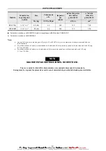
Breaker operating frequency should be 960 blows per minute 
and air consumption 60 CFM (1.85m

3

/min) at 90 psi (6 bar) 

air pressure.

Summary of Contents for IR90VRA

Page 1: ...a Keep work area clean uncluttered ventilated and illumi nated Do not remove any labels Replace any damaged label USING THE TOOL Always wear eye protection when operating or performing maintenance on this tool Always wear hearing protection when operating this tool Always use Personal Protective Equipment appropriate to the tool used and material worked This may include dust mask or other breathin...

Page 2: ... main tain a balanced and firm stance Always use appropriate retainer latch or sleeve in addi tion to proper barriers to protect persons in surrounding or lower areas from possible ejected accessories Never operate a Percussion Tool unless an accessory is properly installed and the tool is held firmly against the work Attach safety cables across hose couplings and fittings and install safety locki...

Page 3: ...in injury For Latch Type Retainer 1 Operate the Latch until it is approximately 90 degrees to the body of the tool and clicks into position 2 Insert the accessory into the tool until the collar of the accessory is past the Latch 3 Operate the Latch until it is parallel to the tool and it clicks into position 30 40 lbs 15 20 kg is the recommended amount of down force to apply to the tool when worki...

Page 4: ...is operating 103 psig 7 1 bar 710 kPa is the Maximum Pressure at the inlet of the tool when it is not operating SAVE THESE INSTRUCTIONS DO NOT DESTROY When the life of the tool has expired it is recommended that the tool be disassembled degreased and parts be separated by material so that they can be recycled Model Shank Size Hex w Collar Weight Air Consumption Impacts per min Certified Sound Powe...

Page 5: ...ants recommandés N utilisez que des solvants de nettoyage appropriés pour nettoyer les pièces Utilisez seulement les solvants répondant aux réglementations de santé et de sécurité en vigeur Uti lisez les solvants de nettoyage dans une zone adaptée Maintenez le lieu de travail propre sans obstruction aéré et bien éclairé Ne retirer aucune étiquette Remplacer toute étiquette endommagée UTILISATION D...

Page 6: ...es fins autres que celles recom mandées Utiliser les accessoires recommandés par Ingersoll Rand Ne pas utiliser un raccord rapide à moins qu il soit séparé de l outil par un flexible fouet Connecter le flexible fouet à l outil à l aide d un raccord série forte à paroi épaisse L outil inséré peut se rompre pendant l usage Se tenir éloi gné et garder une position équilibrée et ferme Utiliser toujour...

Page 7: ... des blessures Douille de retenue à loquet 1 Actionner le loquet jusqu à ce qu il soit à 90 degrés par rapport au corps de l outil et s enclenche en position 2 Insérer le burin dans l outil jusqu à ce que le collet du burin ait dépassé le loquet 3 Ramener le loquet parallèle à l outil pour qu il s enclenche en position 7 10 lbs 15 20 kg est le niveau de force de pression recom mandé à appliquer su...

Page 8: ...pression de fonctionnement maximum recommandée à l admission de l outil lorsqu il ne fonctionne pas CONSERVEZ SOIGNEUSEMENT CES INSTRUCTIONS NE PAS LES DÉTRUIRE A la fin de sa durée de vie il est recommandé de démonter l outil de dégraisser les pièces et de les séparer en fonction des matériaux de manière à ce que ces derniers puissent être recyclés Modèle Emmanchement hexagonal avec collier Poids...

Page 9: ... Use únicamente los lubricantes recomendados Use solamente los disolventes apropiados para la limpieza de las piezas Use solamente los disolventes de limpieza que cumplan las normas vigentes de salud y seguridad Los disolventes de limpieza se deben usar en una zona bien ventilada Mantenga la zona de trabajo limpis despejada ventilada e iluminada No saque ninguna etiqueta Sustituya toda etiqueta da...

Page 10: ...to rápido a menos que esté sepa rado de la herramienta por una manguera de conexión flexible Conecte la manguera flexible a la herramienta uti lizando un racor de paredes gruesas de alto rendimiento La herramienta inserta puede romperse durante el uso Manténgase apartado de la misma y mantenga una pos tura del cuerpo equilibrada y firme Utilice siempre un dispositivo de retención gancho o man guit...

Page 11: ...retenedor tipo palanca 1 Accione el enganche hasta que esté perpendicular al cuerpo de la herramienta y encaje en su posición 2 Introduzca el accesorio en la herramienta hasta que el cuello del accesorio pase el enganche 3 Accione el enganche hasta que esté paralelo a la herramienta y encaje en su posición 7 10 lbs 15 20 kg es la fuerza de impacto recomendada que se debe aplicar a la herramienta m...

Page 12: ...máxima de trabajo en la admisión de la herramienta cuando no está funcionando es de 103 psig 7 1 bar 710 kPa GUARDE ESTAS INSTRUCCIONES NO DESTRUYA Una vez vencida la vida útil de herramienta se recomienda desarmar la herramienta desengrasarla y separar las piezas de acuerdo con el material del que están fabricadas para reciclarlas Modelo Tamaño vás tago exagonal c pinza Peso Consumo de aire Impac...

Page 13: ...ualquer acessório Não lubrifique a ferramenta com líquidos inflamáveis ou voláteis como querosene gasóleo ou combustível para jac tos Utilize apenas os lubrificantes especificados Utilize apenas solventes de limpeza adequados para lim par as peças Utilize apenas solventes de limpeza que obe deçam às normas correntes de saúde e segurança no trabalho Utilize solventes numa área bem ventilada Mantenh...

Page 14: ...ecomendados Use os acessórios recomendados pela Ingersoll Rand Não utilize um acoplamento de desmontagem rápida a menos que este esteja separado da ferramenta por uma mangueira de reforço Ligue a mangueira de reforço à fer ramenta utilizando um acessório para trabalho pesado de paredes espessas A ferramenta inserida pode partir durante a utilização Mantenha se afastado e numa posição equilibrada e...

Page 15: ... Tipo Alavanca 1 Opere a Alavanca até esta estar a 90 graus em relação ao corpo da ferramenta e encaixar em posição 2 Introduza o acessório através do Conjunto do Retentor e instale o na ferramenta 3 Opere a Alavanca até esta estar paralela em relação ao corpo da ferramenta e encaixar em posição A força reomendada para aplicar para baixo durante a utiliza ção da ferramenta é de aproximadamente 30 ...

Page 16: ...psig 7 1 bar 710 kPa é a Pressão máxima na admissão da ferramenta quando esta não está a funcionar CONSERVE ESTAS INSTRUÇÕES NÃO AS DESTRUA Quando a ferramenta não mais funcionar eficazmente recomenda se que a mesma seja desmontada limpa e que as suas peças sejam separadas por tipo de material para poderem ser recicladas Modelo Dimensão da haste sext c anel Peso Consumo de ar Impactos por minuto N...

Page 17: ...17 SERVICE NOTES ...

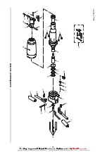
Page 18: ...18 29 41 26 10 9 7 11 14 12 13 10 8 11 5 15 16 17 18 6 24 20 21 25 22 23 31 34 28 30 4 33 27 27 1 2 3 MAINTENANCE SECTION Dwg TP2114 ...

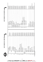
Page 19: ...7 41 Latch Kit 85041317 22 Fronthead Spring Pin Inner 85040962 6 Latch 85040749 23 Fronthead Spring Pin Outer 85040988 20 Plunger 85040939 24 Fronthead Screw 85041002 21 Plunger Spring 85040947 25 Fronthead Nut 85041028 22 Fronthead Spring Pin Inner 85040962 4 Piston 85042489 23 Fronthead Spring Pin Outer 85040988 Handle Assembly 85040715 24 Fronthead Screw 85041002 5 Handle Body 85040723 25 Front...

Page 20: ...LY Using a hide mallet tap loose and remove the muffler 29 from the cylinder Firmly grip the cylinder upright in a vice with leather or cop per covered jaws Loosen the four handle nuts 27 unscrew and remove the four handle screws 26 Lift the handle assembly 5 from the cylinder 1 tap with a hide mallet if necessary Press or tap out the handle pivot pin 12 remove both han dle levers 8 and 9 from the...

Page 21: ...le body Locate the handle springs 11 between hand grips and han dle body and fix the assembly in place by drifting or pressing in handle pivot pin 12 Lubricate the trigger pin 15 trigger ball 16 and replace in the air inlet connection of the handle body Note The trigger pin has a reduced diameter which is placed next to the trigger ball Locate the trigger spring 17 on top of the trigger ball Apply...

Page 22: ...22 SERVICE NOTES ...

Page 23: ...23 SERVICE NOTES ...

Page 24: ...20100 Milano Italy Tel 39 2 950561 Fax 39 2 95380169 Ingersoll Rand Camino de Rejas 1 2 18 B1S 28820 Coslada Spain Tel 34 1 669 5850 Fax 34 1 669 6054 Ingersoll Rand Nederfand Produktieweg 10 2382 PB Zoeterwoude Netherlands Tel 31 71 45220 Fax 31 71 218671 Ingersoll Rand Company SA PO Box 3720 Alrode 1451 South Africa Tel 27 11 864 3930 Fax 27 11 864 3954 Ingersoll Rand Scandinavian Operations Kas...

Reviews: