36
EN
STROLLER SEAT
ATTACHING THE STROLLER SEAT TO THE CHASSIS
fig. 49
Attach the stroller seat (
B3
) to the chassis,
positioning it in the dedicated housings on both sides of the
structure.
fig. 50
Caution: before use, make sure that the stroller
seat is properly attached on both sides by pulling it
upwards.
fig. 51
The stroller seat can be used both rear facing and
forward facing.
DETACHING THE STROLLER SEAT FROM THE CHASSIS
fig. 52
Operate the lever (
C4
) and simultaneously lift the
stroller seat from the chassis.
Caution: do not, under any circumstance, carry out this
operation with the baby inside.
ADJUSTING THE BACKREST
fig. 53
The backrest can be adjusted to 4 positions; use
the central device (
C5
) and bring the backrest to the desired
position.
ADJUSTING THE FOOTREST
fig. 54
To lower the footrest, use both levers (
C6
)
positioned on the lower part and simultaneously press them
downwards.
fig. 55
To lift the footrest, simply pull it upwards and it
shall automatically lock into position.
SAFETY BELTS
fig. 56
Ensure that the safety belts are inserted in the
eyelets at the height of the shoulders or immediately above.
If the position is not correct, remove the belts from the first
pair of eyelets and reinsert them in the second one.
Position both back straps always at the same height.
fig. 57
Connect the ends of the waist straps (
C7
) to the
back harness (
C8
) and complete the attachment by inserting
the end pieces into the central buckle (
C9
).
fig. 58
Always use the waist strap together with the back
harness, adjusting both of them properly.
Caution! Failure to comply with this precaution can cause
the baby to fall or slide out, with serious injury risks.
ATTACHING THE HANDRAIL
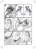
fig. 59
To attach the bumper bar (
C2
), fit it in the dedicated
housings (
C10
) in the stroller seat until it clicks into place.
fig. 60
The handrail can be open on one side or fully
removed; to open it, press the button (
C11
) and remove it
from its housing; to remove it, repeat the procedure on the
other side.
ATTACHING THE STROLLER HOOD
fig. 61
To secure the hood (
C3
), go next to the side joints
(
C12
) on the stroller seat, fit the strap (
C13
) and push strongly
until it clicks completely.
fig. 62
First button the press studs (
C14
) to the side joints
(
C12
), then all rear buttons (
C15
) to the backrest.
fig. 63
To adjust the hood, simply accompany it to the
desired position.
fig. 64
The hood features an additional fabric insert
and sun shade that extend the degree of cover, improving
protection from the sun.
DETACHING THE HOOD FROM THE STROLLER
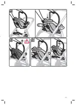
fig. 65
To remove the hood (
C3
) from the stroller seat,
remove all the buttons (
C15
) that secure it to the backrest.
fig. 66
Remove the two snap fasteners (
C14
) that secure
the hood to the side joints (
C12
), then pull the internal strap
(
C13
) from the joints, pulling it firmly from both sides.
HOOD LINING MAINTENANCE
The hood lining can be removed to allow for its correct
maintenance.
fig. 67
Once the hood is released from the stroller, simply
pull out the internal strap (
C13
).
CLOSING THE CHASSIS WITH THE STROLLER SEAT
ATTACHED (STROLLER CONFIGURATION)
The chassis can be closed with the stroller seat attached,
both facing the parent and facing the street.
Facing the parent
fig. 68
Fold the hood, recline the backrest to its most
horizontal position and lift the footrest completely.
fig. 69
Then proceed to fully close the stroller, as detailed
above.
Facing the street
fig. 70
Fold down the hood and bring the backrest fully
forward.
fig. 71
Then proceed to fully close the stroller, as detailed
above.
STROLLER SEAT LINING MAINTENANCE
It is recommended to remove the lining periodically to
provide for its correct maintenance.
To facilitate coating removal, first remove the hood and
handrail.
fig. 72
Remove the cover from the footrest.
fig. 73
First remove the two lower snaps fasteners (
C16
)
that secure the cover to the seat, then the two fasteners
(
C17
) that secure the side panels to the chassis.
fig. 74
Unfasten the two buttons (
C18
) on the backrest
and release the cover from the handrail hooks.
fig. 75
Remove the crotch strap from its protective pad,
releasing it from the locking elastic, then from the slot on the
seat.
fig. 76
Pull the lower back straps out of the slot in the
centre of the backrest.
fig. 77
Remove the lower back straps from both shoulder
straps and release the cover from the side hood joints as well.
fig. 78
After removing the lower back straps from the slots
on the cover, pull it out of the stroller chassis.
REMOVAL/INSTALLATION OF THE SAFETY HARNESS
SYSTEM
The Aptica XT stroller is equipped with a safety harness
system that can be removed if necessary.
fig. 79
To remove the crotch strap, pull the lower ring
(
C19
) out of the slot on the seat (
C20
).
The lower back strap and the two back harnesses are
attached to the backrest by means of safety rings, which are
removed and installed in the same way.
fig. 80
To remove both lower back strap and back harness,
push the belts through the slots on the backrest (
C21
) and
pull firmly until the rings (
C22
) are released from their seats.
Then remove the rings (
C22
) from the slots (
C21
) and pull the
belts out completely.
fig. 81
To install the crotch strap, fit the lower ring (
C19
)
only in the slot on the seat (
C20
). The lower ring (
C23
) must
remain on the outside.
fig. 82
To reassemble both the lower back strap and the
two back harnesses, insert the rings (
C22
) in the appropriate
slots on the backrest and, once they are positioned under
one of the hooking tabs (
C24
), push them firmly into place.
Caution! Position the back harnesses always at the same
height.
fig.
83 Caution! Make sure that all the belts are
correctly attached to the stroller seat by pulling them
individually.
FOOTMUFF (if present)
fig. 84
Position the footmuff (
F
), passing it under the
bumper bar, and attach the press studs (
F1
).
Summary of Contents for APTICA XT
Page 2: ...A ...
Page 4: ...4 1 G F A2 C C3 B2 C2 A2 D E A1 A B C1 B1 ...
Page 5: ...5 2 Click A3 3 4 Click A1 5 6 A1 A4 A3 ...
Page 6: ...6 11 9 10 A7 12 13 A11 A9 A10 8 Click A2 7 LH RH A6 A5 A6 A5 A8 ...
Page 7: ...7 14 A10 15 16 ADAPTIVE CRUISE 19 20 A12 17 A12 18 A13 ...
Page 8: ...8 22 21 A13 23 STOP GO A14 A14 25 A16 24 A15 ...
Page 9: ...9 26 E1 E2 E3 E 28 27 E5 E6 29 E7 E8 E4 ...
Page 10: ...10 30 31 B2 B7 33 32 Click Click 35 34 B3 B4 ...
Page 11: ...11 37 38 36 B1 B4 B3 B5 B6 39 Click 40 B2 ...
Page 12: ...12 45 42 41 B7 43 44 B8 B9 ...
Page 13: ...13 48 46 47 B10 B11 51 49 Click Click 50 B3 ...
Page 14: ...14 53 C5 56 52 C4 54 55 C6 ...
Page 15: ...15 57 Click Click 58 C7 C9 C9 C8 59 Click C2 C10 ...
Page 16: ...16 60 C11 62 61 C15 64 63 C14 C12 C13 C12 C3 ...
Page 17: ...17 65 66 C15 C14 C12 C13 C12 C3 69 Click 67 68 C13 ...
Page 18: ...18 70 71 Click 74 C18 73 72 C16 C17 ...
Page 19: ...19 75 76 77 78 ...
Page 20: ...20 79 C19 C20 80 C21 C22 C21 81 C19 C23 C20 ...
Page 21: ...21 83 CHECK 82 Click C22 C24 84 F F1 ...
Page 22: ...22 88 G2 87 86 85 F2 G G1 ...
Page 23: ...23 89 Click Click 90 91 H ...
Page 177: ...177 ...
Page 178: ...178 ...

