36
EN
RELEASE OF THE HOOD FROM THE STROLLER
fig. 55
To remove the hood (
G
) from the stroller seat,
remove all the buttons (
G1
) that secure it to the backrest.
fig. 56
Remove the two snap fasteners (
G2
) that secure
the hood to the side joints (
G3
), then pull the internal strap
(
G4
) from the joints, pulling it firmly from both sides.
HOOD LINING MAINTENANCE
The hood lining can be removed to allow for its correct
maintenance.
fig. 57
Once the hood is released from the stroller, simply
pull out the internal strap (
G4
).
CLOSING THE CHASSIS WITH THE STROLLER SEAT
ATTACHED (STROLLER CONFIGURATION)
The chassis can be closed with the stroller seat attached,
both facing the parent and facing the street.
Facing the parent
fig. 58
Before closing the stroller, fold the handlebar to the
lowest position.
fig. 59
Fold the hood, recline the backrest to its most
horizontal position and lift the footrest completely.
fig. 60
Then proceed to fully close the stroller, as detailed
above.
Facing the street
fig. 61
Before closing the stroller, fold the handlebar to the
lowest position.
fig. 62
Fold down the hood and bring the backrest fully
forward.
fig. 63
Then proceed to fully close the stroller, as detailed
above.
STROLLER SEAT LINING MAINTENANCE
It is recommended to remove the lining periodically to
provide for its correct maintenance.
To facilitate coating removal, first remove the hood and
handrail.
fig. 64
Remove the cover from the footrest.
fig. 65
First remove the two lower snaps fasteners (
E7
)
that secure the cover to the seat, then the two fasteners (
E8
)
that secure the side panels to the chassis.
fig. 66
Unfasten the two buttons (
E9
) on the backrest and
release the cover from the handrail hooks.
fig. 67
Remove the crotch strap from its protective pad,
releasing it from the locking elastic, then from the slot on the
seat.
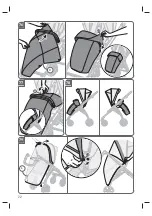
fig. 68
Pull the lower back straps out of the slot in the
centre of the backrest.
fig. 69
Remove the lower back straps from both shoulder
straps and release the cover from the side hood joints as well.
fig. 70
After removing the lower back straps from the slots
on the cover, pull it out of the stroller chassis.
REMOVAL/INSTALLATION OF THE SAFETY HARNESS
SYSTEM
The Electa stroller is equipped with a safety harness system
that can be removed if necessary.
fig. 71
To remove the crotch strap, pull the lower ring
(
E10
) out of the slot on the seat (
E11
).
The lower back strap and the two back harnesses are
attached to the backrest by means of safety rings, which are
removed and installed in the same way.
fig. 72
To remove both lower back strap and back harness,
push the belts through the slots on the backrest (
E12
) and
pull firmly until the rings (
E13
) are released from their seats.
Then remove the rings (
E13
) from the slots (
E12
) and pull the
belts out completely.
fig. 73
To install the crotch strap, fit the lower ring (
E10
)
only in the slot on the seat (
E11
). The lower ring (
E14
) must
remain on the outside.
fig. 74
To reassemble both the lower back strap and the
two back harnesses, after checking that the buckle ends are in
the correct direction, insert the rings (
E13
) in the appropriate
slots on the backrest and, once they are positioned under
one of the hooking tabs (
E15
), push them firmly into place.
Caution! Position the back harnesses always at the same
height.
fig.
75 Caution! Make sure that all the belts are
correctly attached to the stroller seat by pulling them
individually.
FOOTMUFF (IF AVAILABLE)
fig. 76
Position the footmuff (
K
), passing it under the
bumper bar, and attach the press studs (
K1
).
fig. 77
The flap of the footmuff can be extended and
attached in a position suitable for protecting the child from
the cold, fastening it with the external side press studs to the
corresponding elements (
K2
) on the canopy.
fig. 78
The footmuff can be used both facing the parent
and facing the street.
RAIN COVER (IF AVAILABLE)
fig. 79
To fit the rain cover (
L
), position it on the hood and
button both press studs (
L1
) on the sides of the stroller seat.
fig. 80
Then hook the bands (
L3
) around the front tubes,
at the wheel assembly.
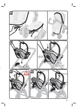
CAB 0+ / DARWIN INFANT i-SIZE INFANT CAR SEAT
(IF AVAILABLE)
ATTACHING THE INFANT CAR SEAT TO THE CHASSIS
fig. 81
Take the infant car seat from the handle and attach
it to the chassis in correspondence of the housings on both
sides of the structure and place it solely facing the parents.
fig. 82
Caution: before use, make sure that the car seat
is properly attached on both sides by pulling it upwards.
DETACHING THE INFANT CAR SEAT FROM THE CHASSIS
fig. 83
Operate the lever (
S1
) on the back of the seat and
simultaneously lift it from the chassis, gripping it with the
handle.
To use the infant car seat properly, refer to the dedicated
manual.
Summary of Contents for ELECTA
Page 2: ......
Page 4: ...4 1 2 T1 B A H J K L E G D F C ...
Page 5: ...5 3 OK NO 4 A 5 6 A A1 7 B B1 CHECK ...
Page 6: ...6 11 9 8 10 T2 T3 T4 CHECK CHECK ...
Page 7: ...7 16 OK NO 15 12 13 14 OK GO NO NO STOP NO T4 T5 T6 B2 CHECK ...
Page 8: ...8 19 18 20 17 T2 H1 H2 H3 H5 H1 H4 H ...
Page 9: ...9 22 21 J1 J 24 23 OK NO C1 25 NO CHECK ...
Page 10: ...10 28 29 26 27 C C4 C3 C5 C2 C6 30 CHECK ...
Page 11: ...11 31 D 33 32 D1 34 35 C6 C7 ...
Page 12: ...12 40 39 OK NO C8 E C9 36 37 38 CHECK ...
Page 13: ...13 41 E2 42 43 NO 44 E1 CHECK ...
Page 14: ...14 48 OK NO NO 45 46 47 E3 ...
Page 15: ...15 49 E5 E6 E4 51 50 F F2 ...
Page 16: ...16 56 55 54 G1 G2 G3 G4 G 52 53 G F1 ...
Page 17: ...17 59 57 58 G4 62 60 61 CHECK ...
Page 18: ...18 66 E9 67 65 63 64 E7 E8 CHECK ...
Page 19: ...19 68 69 70 71 E10 E11 ...
Page 20: ...20 72 E12 E13 E12 73 E11 E14 E10 ...
Page 21: ...21 75 74 E13 E15 OK NO CHECK ...
Page 22: ...22 79 78 77 76 K K1 K2 L L1 ...
Page 23: ...23 80 L3 81 83 82 S1 CHECK ...
Page 170: ...170 ...

