14
Technical description
Power supply stations
Note:
INIM s.r.l. reserves the right to change, replace, in part or entirely, the components not strictly relating
to the installation procedure described in Chapter 5 - Installation instructions.
4.3
Signalling LEDs
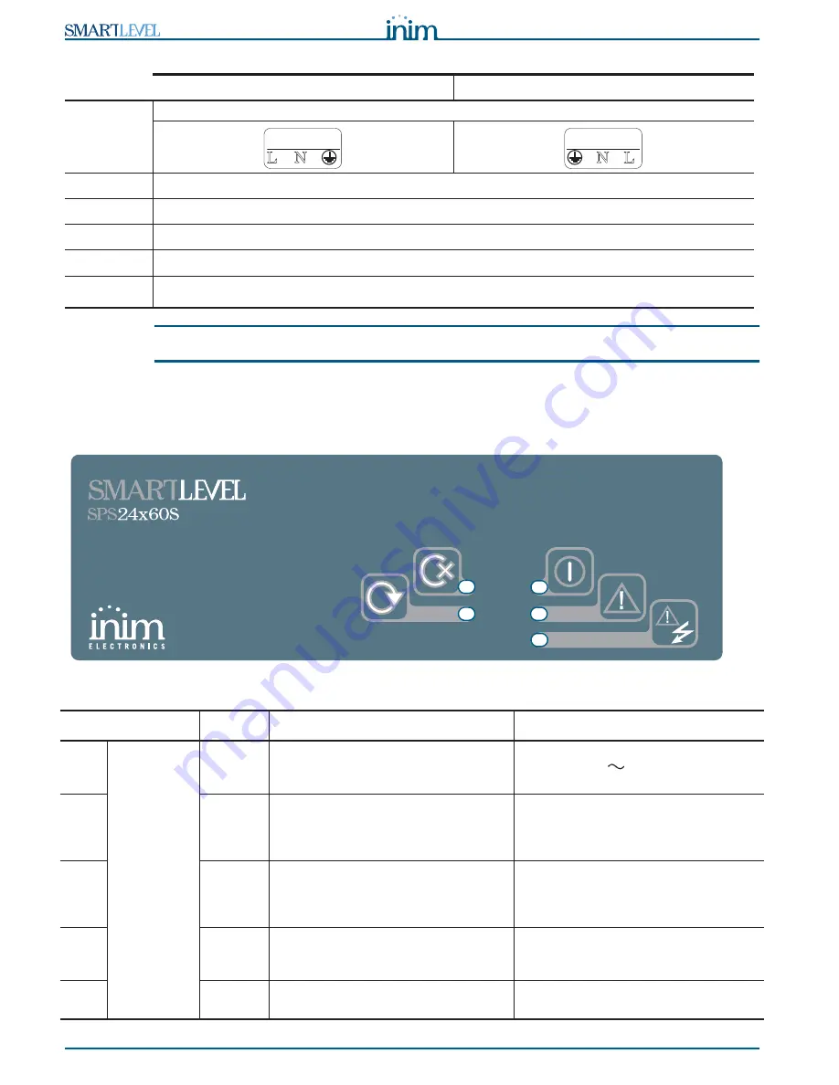
The user can access the SmartLevel stations through the two relay outputs available on the motherboard
and the LEDs on the front panel and on the switching power supply:
Figure 7 - Front panel
SPS24060S
SPS24160S
[A]
Mains input terminal board
[B]
SmartLevel mother board connector
[C]
Battery connector
[D]
Thermal probe connector
[E]
Signaling LEDs
[F]
Ground fault signaling jumper input
(if the jumper is removed, earth faults will not be signaled)
LED
Colour
Signalling
Note
[A]
Frontplate
green
Indicates the power station is working.
This LED will go Off in the event of joint
primary (230V
) and secondary
(batteries) power failure.
[B]
yellow
Indicates an active fault condition.
This condition activates the “FAULT”
relay.
For further details, see the LED
activation on the power-supply unit.
[C]
yellow
Indicates an active mains fault
condition.
This condition activates the “MAINS”
relay.
For further details, see the LED
activation on the power-supply unit.
[D]
yellow
Indicates an active fault condition or a
short-circuit in the loop.
For further details, see the fire-
detection control panel that supervises
the loop.
[E]
green
Indicates active communication though
the loop.
N
L
230V ~ 50/60 Hz
AC Input
N L
230V ~ 50/60 Hz
AC Input
B
A
C
D
E


