12
I
Inverter Parameters
Inverter Parameters
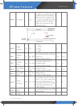
P 09
Stop Mode
0 or 1
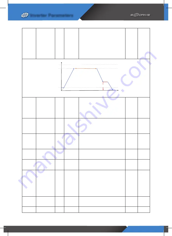
- 0 (Ramp to stop): When the enable
signal is removed, the drive will ramp to
stop, with the rate controlled by P-08.
- 1 (Coast to Stop): When the enable
signal is removed, or if the mains
supply is lost, the motor will coast
(freewheel) to stop.
1
1
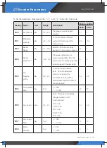
P 10
PUMP
Capacity
HP
0 - 4
- 0: 1HP
- 1: 1.5HP
- 2: 2HP
- 3: 2.5HP
- 4: 3HP
2
2
P 11
Overload
Rate
%
50 - 200
Trip current level against rated current
of the motor.
(Protection related to Motor)
150
150
P 12
Overload
Time
Sec
2.0 - 99.9
It sets the maintaining time of
overload trip level.
(Protection related to Motor)
10
10
P 13
Over-Voltage
Rate
%
100 - 200
[%]
Voltage is too high.
(Protection related to Inverter)
120
120
P 14
Low-Voltage
Rate
%
50 - 90
[%]
Voltage is too low.
(Protection related to Inverter)
60
60
P 15
Carrier
Frequency
KHz
3.0 - 15.0
It is possible to choose in the range
of 2.5 ,4, 6, 8, 10 kHz. Higher values
give a more sinusoidal wave with
fewer losses for the motor but higher
losses for the inverter (increased
inverter heating).
8
8
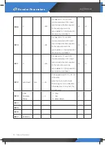
P 16
TEST
- 444: reset (VFD can be re-set to the
factory setting)
P 17
VERSION
0
F
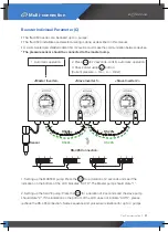
Time
Delay Time(5sec.)
Min. output
Frequency
Max.Freq.(60Hz)
Accel.
Decel.
PID Control
Ramp to stop
Coast to Stop
Setting operation
ACC/DEC TIME


