background image


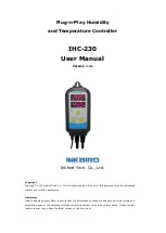
IHC-230 User Manual


Inkbird Tech. Co., Ltd.                                                                        www.ink-bird.com


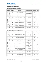
5.1 Control Range Setting  

MD: Mode Setting 

MD=H, being in Humidity Setting Mode, user can set humidity parameters in the following 

menu; 

MD=T,  being  in  Temperature  Setting  Mode,  user  can  set  temperature  parameters  in  the 
following menu; 


5.2 Humidity/Temperature Control (HD, HS, DS/ HC,TS,DS) 

In Humidifying/Heating Control Mode (HD=H, HC=H) 

When  the  measured  humidity  (temperature)  drops  down  to 

HS–DS  (or  TS-DS)

,  the 

output  will  be  on  and  the  indicator  lamp  will  light  up;  When  the  measured 

humidity/temperature  reaches  the  set  value 

HS  (TS)

,  the  output  will  be  off  and  the 

indicator lamp will be off too. 


In Dehumidifying/Cooling Control Mode (HD=D, HC=C) 

When the measured humidity (temperature) rises to 

HS+DS (or TS+DS)

, the output will 

be  on  and  the  indicator  lamp  will  light  up;  when  the  measured  humidity/temperature 

reaches the set value 

HS (TS)

, the output will be off and the indicator lamp will be also off. 


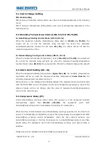
5.3 Alarm Limit Setting (AH, AL) 

When the measured humidity (temperature) 

higher than AH

, the humidity (temperature) 

high  alarm  will  be  on;  when  the  measured  humidity  (temperature) 

lower  than  AL

,  the 

humidity (temperature) low alarm will be on. 

When alarm is on, the display will be flashing between the measured value and alarm code 

with the “BI-BI-BIII” sound. The alarm sound can be stopped by pressing any key but the 
status  of  alarm  will  be  not  change  until  the  value  of  measured  humidity/temperature 

return to the normal range.  


5.4 Compressor Delay (PT) 

Under  dehumidifying  (cooling)  control  mode,  after  power  on,  if  the  measured  humidity 

(temperature)  higher  than 

HS+DS 

(TS+DS)

,  the  equipment  won’t  start 

dehumidifying/cooling control immediately, but waiting for a delay time.  
 

When the time interval between two dehumidifying (cooling) operation (or the time from 

power on to dehumidify (refrigeration) is larger than preset delay, the equipment will start 

dehumidifying  (cooling)  control  immediately;  when  the  time  interval  between  two 
dehumidifying (cooling) (or the time from power on to dehumidifying/cooling) is less than 

preset  delay,  the  equipment  won’t  start  dehumidifying  (cooling)  until  preset  delay  is 

satisfied.  
 

Delay time will be calculated once dehumidifying (cooling) stops.  

Summary of Contents for IHC-230

Page 1: ...served No part of this document may be reproduced without prior written permission Disclaimer Inkbird has made every effort to ensure that the information contained in this document is accurate and complete however the contents of this document are subject to revision without notice Please contact Inkbird to ensure you have the latest version of this document ...

Page 2: ...ow to Set Parameters 6 4 3 Setup Flow Chart 7 5 Menu Instruction 8 5 1 Control Range Setting 9 5 2 Humidity Temperature Control HD HS DS HC TS DS 9 5 3 Alarm Limit Setting AH AL 9 5 4 Compressor Delay PT 9 5 5 Calibration CA 10 5 6 Display in Fahrenheit or Centigrade unit CF 10 6 Error Description 10 Sensor Fault Alarm 10 7 Technical Assistance and Warranty 11 7 1 Technical Assistance 11 7 2 Warra...

Page 3: ...oduct Doing so may occasionally result in electric shock fire or malfunction DO NOT use the product where subject to flammable or explosive gas Otherwise injury from explosion may occasionally occur DO NOT disassemble modify or repair the product or touch any of the internal parts Electric Shock fire or malfunction may occasionally occur If the output relays have been used over their life expectan...

Page 4: ...dity 12A 100 240VAC Temperature 12A 100 240VAC Input Power Cable Length 1 5m 5ft Output Power Cable Length 30cm 1ft Dimension Main Body 140x68x33mm 5 5x2 7x1 3 inch Socket US Version 85x42x24mm 3 3x1 7x1 0 inch Socket EU Version 135x54x40mm 5 3x2 1x1 6 inch Socket UK Version 140x51x27mm 5 5x2 0x1 0 inch Ambient Temperature 30 75 C 22 167 F Storage Temperature 30 75 C 22 167 F Humidity 20 85 No Con...

Page 5: ... Cooling and dehumidifying devices Alarm will be on when temperature or humidity exceeds high low alarm setting value 3 Keys Instruction Window 1 Temperature measuring Value or Setting Menu Code Window 2 Humidity Measuring Value or Setting value Temperature Indicator Lamp Work1 On Working Off Stop Working Flickering Delay Output Humidity Indicator Lamp Work2 On Working Off Stop Working Flickering ...

Page 6: ...ow to Set Parameters Under running mode press and hold SET key for 3 seconds to enter parameters setting mode window1 displays the first menu code MD while window2 displays according setting value Press SET key to page down the menu then the code will display press key to change the current parameter values After finished settings press and hold key for 3 seconds at any status to save the paramete...

Page 7: ...IHC 230 User Manual Inkbird Tech Co Ltd www ink bird com 7 4 3 Setup Flow Chart ...

Page 8: ...y Protected Delay Only for Dehumidifying 0 10Minute 0 5 3 CA Humidity Calibration Offset 15 15 RH 0 5 4 When MD T Temperature setting mode Symbol Code Function Setting Range Default Note HC Temperature Control Mode H Heating C Cooling H 5 1 TS Temperature Set Value 40 100 40 212 25 DS Temperature Control Differential 1 20 2 AH Temperature High Limit Alarm 40 100 40 212 100 5 2 AL Temperature Low L...

Page 9: ...midity temperature higher than AH the humidity temperature high alarm will be on when the measured humidity temperature lower than AL the humidity temperature low alarm will be on When alarm is on the display will be flashing between the measured value and alarm code with the BI BI BIII sound The alarm sound can be stopped by pressing any key but the status of alarm will be not change until the va...

Page 10: ... degree displaying can be selected as needed Default displaying is in Centigrade degree Please set CF to F to change the displaying in Fahrenheit degree if needed Attentions After CF value changed all the setting value will be recovered to factory settings 6 Error Description Sensor Fault Alarm when sensor is being in short circuit or open loop the controller will initiate sensor fault mode by sto...

Page 11: ...ondition by the original purchaser not transferable against defects caused by INKBIRD s workmanship or materials This warranty is limited to the repair or replacement at INKBIRD s discretion of all or part of the thermostat The original receipt is required for warranty purposes INKBIRD is not responsible for injury property damage or other consequential damages or damages of third parties arising ...

Reviews: