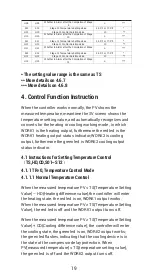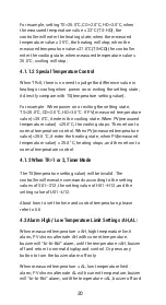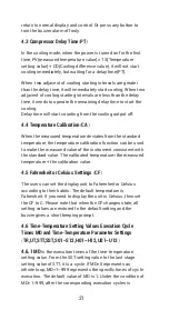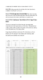
18
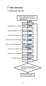
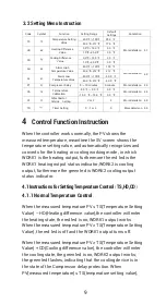
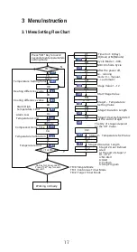
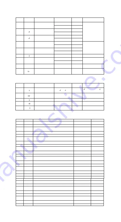
3.2 Setting Menu Instruction
Code
Symbol
Function
Setting Range
Default
Settings
Annotation
TS
tS
Temperature Setting
Value
-40.0
℃~
100
℃
25.0
℃
-40.0
℉
~212
℉
77.0
℉
℉
HD
H
Heating Difference
Value
0.3
℃~
15.0
℃
2.0
℃
1.0
℉
~30.0
℉
3.0
℉
℉
CD
C
Cooling Difference
Value
0.3
℃~
15.0
℃
2.0
℃
1.0
℉
~30.0
℉
3.0
℉
AH
AH
Alarm High
Temperature Value
-40.0
℃~
100
℃
100
℃
-40.0
℉
~212
℉
212
℉
℉
3.2.1 When TR=1 or 2, menu code setting is as below.
Code
Symbol
Function
Setting Range
Default
Settings
Annotation
UT
U
Time Unit Setting
Value
D
:
Day,
:
Hour,
:
Minute
MD
Cycle Setting Value
0-999
1
When is 00
,
in
fin
ite
loop
AT
A
Auto or Manual Mode
0 or 1
0
0:Manually, 1:Automatic
STT
S
Time Stage Setting
Value
1-12
1
More details on 4.6.4
SST
SS
Start Stage Settings
Value
1~12
1
More details on 4.6.5
3.2.2 When STA is set to 12, menu code setting is as below.
Code
Symbol
Function
Default Settings
Annotation
S01
S01
Stage 1 Temperature Setting Value
25.0
℃
or 77.0
℉
*
H01
H01
Stage 1 Control Duration Value
10
**
U01
U01
Whether to Alarm after the Completion of
Stage1
n
***
S02
S02
Stage 2 Temperature Setting Value
25.0
℃
or 77.0
℉
*
H02
H02
Stage 2 Control Duration Value
10
**
U02
U02
Whether to Alarm after the Completion of Stage
2
n
***
S03
S03
Stage 3 Temperature Setting Value
25.0
℃
or 77.0
℉
*
H03
H03
Stage 3 Control Duration Value
10
**
U03
U03
Whether to Alarm after the Completion of Stage
3
n
***
S04
S04
Stage 4 Temperature Setting Value
25.0
℃
or 77.0
℉
*
H04
H04
Stage 4 Control Duration Value
10
**
U04
U04
Whether to Alarm after the Completion of Stage
4
n
***
S05
S05
Stage 5 Temperature Setting Value
25.0
℃or
77.0
℉
*
H05
H05
Stage 5 Control Duration Value
10
**
U05
U05
Whether to Alarm after the Completion of Stage
5
n
***
S06
S06
Stage 6 Temperature Setting Value
25.0
℃
or 77.0
℉
*
H06
H06
Stage 6 Control Duration Value
10
**
U06
U06
Whether to Alarm after the Completion of Stage
n
***
AL
AL
Alarm Low
Temperature Value
-40.0
℃~
100
℃
-40.0
℃
-40.0
℉
~212
℉
-40.0
℉
PT
P
Compressor Delay
0
~
10 minutes
0 minute
More details on 4.3
CA
CA
Temperature
Calibration
-9.9
℃~
9.9
℃
0.0
℃
More details on 4.4
More details on 4.1
More details on 4.2
-15.0
℉
~15.0
℉
0.0
℉
CF
CF
Fahrenheit or Celsius
Setting
C or F
F
More details on 4.5
TR
Timer Setting
0
、
1 or 2
0
More details on 4.6.2
6
S07
S07
Stage 7 Temperature Setting Value
25.0
℃
or 77.0
℉
*
H07
H07
Stage7 Control Duration Value
10
**
U07
U07
Whether to Alarm after the Completion of Stage
7
n
***
S08
S08
Stage 8 Temperature Setting Value
25.0
℃
or 77.0
℉
*
H08
H08
Stage 8 Control Duration Value
10
**
U08
U08
Whether to Alarm after the Completion of Stage
8
n
***
S09
S09
Stage 9 Temperature Setting Value
25.0
℃
or 77.0
℉
*
H09
H09
Stage 9 Control Duration Value
10
**
H
H
Summary of Contents for ITC-608T
Page 1: ...ITC 608T Manual...
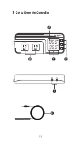
Page 7: ...5 86 8f 96 0f WORK1 WORK2 A B C D E F P1 P2 1 Get to Know the Controller...
Page 15: ...13 86 8f 96 0f WORK1 WORK2 A B C D E F P1 P2 1 Get to Know the Controller...
Page 28: ...26 DUAL TEMPERATURE PROBES Controller Manual ITC 608T Part 4...
Page 29: ...27 WORK1 WORK2 A B C D E F P1 P2 1 Get to Know the Controller 88 6f 98 6f...
Page 38: ...36 HUMIDITY Controller Manual Equivalent to IHC 200 Humidity Controller Manual ITC 608T Part 5...
Page 39: ...37 56 8 66 0 WORK1 WORK2 A B C D E F P1 P2 1 Get to Know the Controller...
Page 46: ...44 WORK1 WORK2 A B C D E F P1 P2 1 Get to Know the Controller 88 6f 56 8...

