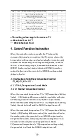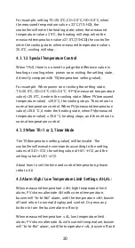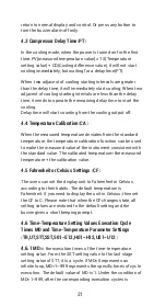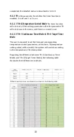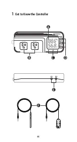
33
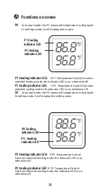
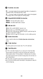
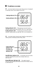
Functions on screen
PV
:
In normal mode, the measured humidity is displayed. In
settings mode, it will display menu code.
SV
:
In normal mode, the humidity setting value is displayed.
In setting mode, it will display the setting value.
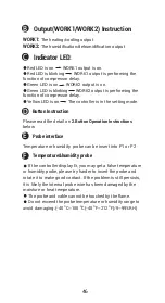
Output(WORK1/WORK2) Instruction
WORK1:
The humidif ication output
WORK2:
The dehumidif ication output
Indicator LED:
●
Red LED is on
WORK1 output is on.
●
Green LED is on
WORK2 output is on.
●
Green LED is blinking
WORK2 output is performing the
function of compressor delay.
●
Yellow LED is on
The controller is in the setting mode.
Button Instruction
Please read the detail on
2.Button Operation Instructions
below
Probe interface
Humidity probe can be insert into P1 or P2 interface.
humidity probe
If the controller display Er, you may get a false humidity
probe, please try harder to insert the probe and rotate it to
make good contact. If the problem is still persists, it is likely
the internal probe wire has been damaged by the moisture or
heat temperature.
The probe and cable cannot be touched by the flame.
Do not exceed the probe humidity or temperature range to
avoid damaging
2
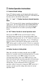
Button Operation Instructions
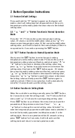
2.1 Restore Default Settings
Press " " button to power on, the buzzer will make a short
call, indicating that all parameters of the user's humidity probe
function return to the default setting value.
2.2 “ ” and “ ”Button Function in Normal Operation
Mode
Press " ", PV shows HD, SV shows humidif ication difference
value; press " ", PV shows DD, SV shows dehumidification
difference value, and it will be back to the normal display if
there is no operation for 3 seconds or pressing the "
SET
"
button.
2.3 “SET” Button Function in normal operation mode
Short press the “
SET
” button to enter the quick setting
humidity setting value mode. SV shows the humidity value
and flashes, and short press “ ” or “ ” button to increase or
decrease the setting value, long press “ ” or “ ”button to
quickly increase or decrease the setting value, and press the
"
SET
" button again to confirm and exit. If there is no operation,
it will automatically exit after 10 seconds and save the setting
value.
2.4 Button Function in Setting Mode
When the controller is working normally, press the “
SET
”
button for 2 seconds to enter the setting mode, the PV screen
shows the first menu code “
HS
” and the SV shows the
corresponding setting value. Press “
SET
” button to scroll
down the menu item and save the parameters of the previous
menu item. Press “ ” or “ ”button to change the current
setting value. If in the setting state, there is no button
operation within 30 seconds or long press "
SET
" button for 2
seconds, exit and save the setting state, return to normal
operation mode.
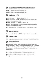
Output(WORK1/WORK2) Instruction
WORK1:
The P1 heating/cooling output
WORK2:
The P2 heating/cooling output
Indicator LED:
●
Red LED is on WORK1 output is on.
●
Red LED is blinking WORK1 output is performing the
function of compressor delay.
●
Green LED is on WORK2 output is on.
●
Green LED is blinking WORK2 output is performing the
function of compressor delay.
●
Yellow LED is on The controller is in the setting mode.
Button Instruction
Please read the detail on
2.Button Operation Instructions
below
Probe interface
Two temperature probes can be insert into P1 and P2 interface.
Temperature probe
●
If the controller display Er, you may get a false temperature
probe, please try harder to insert the probe and rotate it to make
good contact. If the problem is still persists, it is likely the
internal probe wire has been damaged by the moisture or heat
temperature.
●
The probe and cable cannot be touched by the flame.
●
Do not exceed the probe temperature range to avoid
damaging.
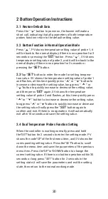
2 Button Operation Instructions
2.1 Restore Default Settings
Press and hold the “ " button to power on, the buzzer will
make a short call, indicating that all parameters of the user's
temperature and humidity probe function return to the default
setting value.
2.2 “ ” and “ ”Button Function in Normal Operation
Mode
Press the “ ", PV shows the current temperature setting
value , SV shows current humidification value; press “ ", PV
shows current temperature value, SV the current humidification
setting value , and It will be back to the normal display if there is
no operation for 3 seconds orpressing the "
SET
" button.
2.3 “SET” Button Function in Normal Operation Mode
Short press the “
SET
” button to enter the quick setting
temperature and humidity value mode. PV shows the current
temperature setting value and flashes, and short press “ ” or
“ ” button to increase or decrease the setting value, long
press “ ” or “ ”button to quickly increase or decrease the
setting value, Short press the “
SET
” button again
,
SV shows
the current humidity setting value and flashes, and short press
“ ” or “ ” button to increase or decrease the setting value,
long press “ ” or “ ”button to quickly increase or decrease
the setting value and lastly press the "
SET
" button again to
confirm and exit. If there is no operation, it will automatically
exit after 10 seconds and save the setting value.
2.4 Button Function in Setting Mode
When the controller is working normally, press the “
SET
” button
for 2 seconds to enter the setting mode
,
the PV shows the first
menu code“
”, SV shows the corresponding setting value.
Press “
SET
” button to scroll down the menu item and save the
parameters of the previous menu item. Press“ ” or
“ ”button to change the current setting value. Selected T to
enter the temperature parameter modification mode; selected H
to enter the humidity parameter modification mode. If in the
setting state, there is no operation within 30 seconds or long
press "
SET
" button for 2 seconds, it will exit and save the
setting state and return to normal operation mode.
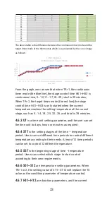
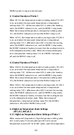
WORK2 probe 2 output state indicator.
4.1 Control Function of Probe 1
When HC1=H, the temperature mode is heating mode, PV LED 1
is on, and when the measured temperature ≤ temperature
setting value TS1 - difference value DS1, it enters the heating
state, the WORK1 indicator is on, and the WORK1 relay works.
When the measured temperature ≥ temperature setting value
TS1, the WORK1 indicator is off and the WORK1 relay is off.
When HC1=C, the temperature mode is cooling mode, PV LED 2
is on, and when the measured temperature ≥ temperature
setting value TS1 + difference value DS1, it enters the cooling
state, the WORK1 indicator is on, and the WORK1 relay works;
the WORK1 indicator flashes,it means that the cooling device is
in the delayed protection state. When the measured tempera-
ture ≤ temperature setting value TS1, the WORK1 indicator is
off and the WORK1 relay is off.
4.2 Control Function of Probe 2
When HC2=H, the temperature mode is heating mode, SV LED1
is on, and when the measured temperature ≤ temperature
setting value TS2 - difference value DS2, it enters the heating
state, the WORK2 indicator is on, and the WORK2 relay works.
When the measured temperature ≥ temperature setting value
TS2, the WORK2 indicator is off and the WORK2 relay is off.
When HC2=C, the temperature mode is cooling mode, SV LED 2
is on, and when the measured temperature ≥ temperature
setting value TS2 + difference value DS2, it enters the cooling
state, the WORK2 indicator is on, and the WORK2 relay works;
the WORK2 indicator flashes, it means that the cooling device
is in the delayed protection state. When the measured
temperature ≤ temperature setting value TS2, the WORK2
indicator is off and the WORK2 relay is off.
4.3 High/Low Temperature Alarm Settings
(
AH1,AL1,AH2,AL2
)
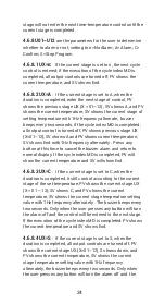
4.3.1 High/Low Temperature Alarm Settings of Probe 1
When measured temperature ≥ high temperature setting value
AH1, it will alarm, PV shows alternate AH1 with current
temperature, buzzer will “bi-bi-Biii” alarm, until the temperature
Summary of Contents for ITC-608T
Page 1: ...ITC 608T Manual...
Page 7: ...5 86 8f 96 0f WORK1 WORK2 A B C D E F P1 P2 1 Get to Know the Controller...
Page 15: ...13 86 8f 96 0f WORK1 WORK2 A B C D E F P1 P2 1 Get to Know the Controller...
Page 28: ...26 DUAL TEMPERATURE PROBES Controller Manual ITC 608T Part 4...
Page 29: ...27 WORK1 WORK2 A B C D E F P1 P2 1 Get to Know the Controller 88 6f 98 6f...
Page 38: ...36 HUMIDITY Controller Manual Equivalent to IHC 200 Humidity Controller Manual ITC 608T Part 5...
Page 39: ...37 56 8 66 0 WORK1 WORK2 A B C D E F P1 P2 1 Get to Know the Controller...
Page 46: ...44 WORK1 WORK2 A B C D E F P1 P2 1 Get to Know the Controller 88 6f 56 8...

