background image

7-9-2 M

ECHANICAL 

A

LIGNMENT OF THE 

P

RINT 

H

EAD 


After the all the Gen 4 heads are installed onto the printer and ink are supplied. You need to align the 
mechanical position of the five print heads according to the CheckNozzle pattern, so that they cooperate 
well. 

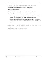
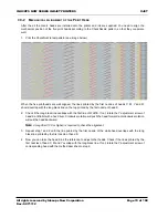
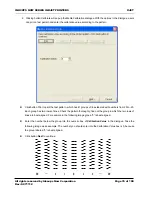
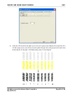
1.  Print the CheckNozzle test pattern (see image below). 


When the five printheads are well aligned, the lines printed by the first nozzles of heads C, M, Y and W 
should overlap with the long black line on the top printed by the first nozzle of head K.   

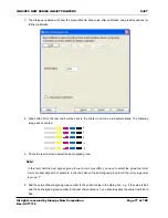
2.  Check if the long black line overlaps with the first line of WHITE. If not, rotate the Y adjustment screw of 

head K a little bit with a hex driver. Clockwise rotation will push the head forward; anti-clockwise rotation 
will pull the head backward. 

Note: A magnifier (10X or higher) is required to check the alignment. 

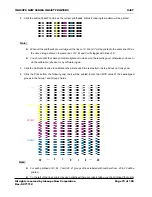
3.  Repeat step 1 and 2 until the line printed by the first nozzle of the white head overlaps with the long 

black line printed by the first nozzle of head K. 

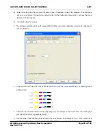
4.  Now you can take the head K as the reference to adjust other heads. Check if the lines printed by the 

first nozzles of head C, M and Y overlap with the long black line. If not, rotate the Y adjustment screw of 
corresponding head with the method described in step 2. 


INKCUPS NOW SERIES INKJET PRINTERS

XJET

All rights reserved by Inkcups Now Corporation 

Rev: SC71112

Page 74 of 100

Summary of Contents for XJET

Page 1: ...www inkcups com SERVICE MANUAL...

Page 2: ...this document or for any direct indirect incidental or other consequential damages resulted from using this material ICN owns the properties of trademarks photographs and technical terms in this docum...

Page 3: ...wer Supply 13 2 1 1 Main Power Control Strong Current 13 2 1 2 DC Power Distribution 15 2 2 SYSTEM REQUIREMENTS 16 2 3 PCB Boards 17 2 3 1 Board List 17 2 3 2 Head Board 4 Colors W 18 2 3 3 IS Main Bo...

Page 4: ...3 Workflow 43 4 4 Setting Negative Pressure Value 44 CHAPTER 5 PRINTER CONTROL INTERFACES 45 5 1 Printer Control Software 45 5 2 Using LCD Control Panel 47 CHAPTER 6 PREPARATION AND PRINTER SETUP 49 6...

Page 5: ...Plate Assembly 63 7 5 Assemble Print Heads with Ink Tubes 65 7 6 Install Assembled Print Heads on Head Plate 66 7 7 Installing the Head Plate onto Carriage 68 7 8 Connect Print Heads to the Ink System...

Page 6: ...5 8 3 4 Before Printer Power Off 96 CHAPTER 9 CARRIAGE TRANSMISSION BELT ADJUSTMENT 97 9 1 Checking the Tension of Carriage Transmission Belt 97 9 2 Adjusting Carriage Transmission Belt 98 APPENDIX A...

Page 7: ...o ground the printer may result in electrical shock fire and susceptibility to electromagnetic interference Use only the electrical cord supplied with the printer Do not damage cut or repair the power...

Page 8: ...responsibility of users to comply with these regulations Manufacturer recommends installing with an ink vapor extraction and exhausting system or a certified air purification system Before installing...

Page 9: ...and electrical shock and cause malfunction Do not clean the printer with benzene or paint thinner which may damage the paint Never touch the print head nozzles They can be easily damaged or clogged R...

Page 10: ...e transmission are installed Printing Gantry The whole gantry moves in Y direction during printing Adjustable Foot Hold the printer and make sure printer s base is horizontal Caster Facilitates printe...

Page 11: ...rol Drive the rolling of conveyor including belt roller motor reducer and a rotary encoder Meniscus Control Cabinet Includes NP Control Board air pumps air valves air cylinder etc All rights reserved...

Page 12: ...on Belt Drives the carriage moving in X axis PWC Automatic wiping and capping unit for print head maintenance LED UV Lamps Light during printing to cure printouts Head Plate with Ricoh Gen 4 Print Hea...

Page 13: ...switched Pease check with your technical support or sales if the Relay installed on the printer is for 220V P N ECPS0087 or 110V P N ECPS0190 Please check with your technical support or sales if the P...

Page 14: ...Connection Illustration INKCUPS NOW SERIES INKJET PRINTERS XJET All rights reserved by Inkcups Now Corporation Rev SC71112 Page 13 of 100...

Page 15: ...V for IS Main Board PWC Board Negative Pressure Control Board UV Adapter Board and platen fans 36V for X Y and Z servo motors 12V for the head board 48V for the two LED UV lamps INKCUPS NOW SERIES INK...

Page 16: ...B Hard Disk 230 GB Operating System Windows 7 64 bit Monitor 1024x768 Pixels USB port High speed USB 2 0 port USB cable High grade USB 2 0 cable We recommend you to use NTFS file system to deal with f...

Page 17: ...ty Image Head Board 6H V6 0 1 IS Main Board V4 6 1 Negative Pressure control board V2 0 1 UV Adapter Board V2 4 1 PWC Board V1 3 1 INKCUPS NOW SERIES INKJET PRINTERS XJET All rights reserved by Inkcup...

Page 18: ...gh printhead adaptor cables communicates with IS main board and receive signals of ink level in sub tanks JP613 JP617 W Y M CK Even ODD Head K Even ODD Head C Even ODD Head M Even ODD Head Y Even ODD...

Page 19: ...will not print correctly Warning Make sure the plugging cards of print head data cables are fully plugged into the corresponding sockets and locked otherwise print head may get burned Socket Connecti...

Page 20: ...for the loading of fixture Arm232 to Step Driver Board CANBUS to NP Board J401 Power Supply P3 P8 Ink Pumps P18 P Pump P19 20 Buzzer P13 P14 Ink Pumps Z to Z limit sensors X Y Step X org X end MS4 MS...

Page 21: ...o Y direction end sensor Y encoder Z To Z direction origin and end sensor Z Servo To linear encoder and motor driver of platen movement in Z axis and also the through beam photoelectric sen Ink Supply...

Page 22: ...te 1 Sen8 From Main Ink Tank of White 2 UV Lamp Control PS1 To JP301 of UV Control Board PS2 PS3 P9 P12 To JP301 of UV Control Board BD SF F1 F2 To JP301 of UV Control Board Power Control INKCUPS NOW...

Page 23: ...ence board Z FD Others ARM232 To JP211 of Step Driver Board JP601 To JP301 of head board P19 P20 To Buzzer Panel To JP2 of LCD Board Simple Panel To JP4 of Fan SMC Board USB To computer installed with...

Page 24: ...P101 From power supply JP401 To the step motor driver of conveyor Z Servo From the rotary encoder of conveyor Z Servo JP101 JP205 JP401 INKCUPS NOW SERIES INKJET PRINTERS XJET All rights reserved by I...

Page 25: ...IS Main Board JP2 Wire 01 to Stop button wire L1 to relay JP3 From L1 and N terminals of terminal block JP4 To PS4 of IS Main Board JP1 JP4 JP3 JP2 INKCUPS NOW SERIES INKJET PRINTERS XJET All rights...

Page 26: ...t Pin5 Lamp 1 On Pin6 Lamp 2 On Pin7 Lamp 1 Set Power Bit1 Pin8 Lamp 2 Set Power Bit1 Pin9 GND Pin11 Lamp1 shutter open Pin12 Lamp 2 Fault Pin13 Lamp 1 Shutter Run LED EN A In Pin14 GND Pin19 Lamp 1 S...

Page 27: ...dback Pin30 Lamp 2 Shutter Open Feedback Pin31 Lamp 2 Shutter Closed Feedback Pin35 Lamp 1 Set Power Bit2 JP601 To LED UV lamp 1 JP602 To LED UV lamp 2 INKCUPS NOW SERIES INKJET PRINTERS XJET All righ...

Page 28: ...IS Main Board JP301 KCMY Pin 1 3 5 24V Pin 2 to positive 3 way EM valve Pin 4 to negative 3 way EM valve Pin 6 to negative pump JP302 White U301 Negative pressure sensor of Meniscus system of KCMY U3...

Page 29: ...JP1A To the PWC s motor of Y direction movement A A B B JP1B To the PWC s motor of X direction movement JP201 From the down sensor of PWC JP202 From the up sensor of PWC JP203 From X origin sensor of...

Page 30: ...Panel of IS Main Board JP5 From main ink tanks of K and C JP5 JP6 GND K C GND M Y Waste F JP6 From main ink tanks of M Y flushing fluid and waste ink INKCUPS NOW SERIES INKJET PRINTERS XJET All right...

Page 31: ...It is installed at the left end of carriage s guide beam 2 DC Motor Driver It sits in the front electric cabinet It controls and drives the DC motor Three connectors are plugged on the DC motor driver...

Page 32: ...or Carriage Stops Moving Carriage moves right ward and check if the origin sensor is effective No Continue searching for origin sensor 15S Carriage Stops Moving Yes Y Gantry Initialization End Printin...

Page 33: ...its passage is linear One each linear guide there are four guide sliders two for each connecting plate 4 Step Motor Driver It sits in the front electric cabinet It controls and drives the step motor...

Page 34: ...ion Z Axis Initialization Error Printing Gantry Stops Moving Printing gantry moves backward and check if the Y origin sensor is effective No Continue searching for Y origin sensor Printing Gantry Stop...

Page 35: ...and couplings 4 Pneumatic Supports and Shafts They hold the printing platen and make printing platen s movement in Z axis possible and stable There are two pneumatic supports and two shafts at each en...

Page 36: ...tialization Error Platen Stops Moving Printing platen moves down and Check if the Z origin sensor is effective No Continue searching for Z origin sensor Printing platen stops at the Z origin position...

Page 37: ...ovement in Y direction 1 Two connectors are plugged on the step motor driver The signal cables PUL PUL DIR and DIR go to the main board encoder and high voltage cables EB EB EA EA 5V and GND come from...

Page 38: ...nthead maintenance and negative pressure to stablize ink supply for high speed printing The positive and negative pressures are controlled by the air system which is introduced in Chapter 4 Please see...

Page 39: ...on the main ink tank to prevent any dust from getting in Two Ink disk filters are also required before the ink getting into sub ink tank and printheads to filter any dust and air And the needle filter...

Page 40: ...id ink from flowing back Sub ink tanks It is designed for stable ink supply Two level sensor is installed in each sub tank When the sensors detect that ink level is low ink pumps will pump ink from ma...

Page 41: ...ssure Control Board that gives orders Inflation Valve It triggers the negative pressure pump to pump It connects to JP301 or JP302 on negative pressure control board that orders the valve to inflate w...

Page 42: ...rge button Adjustable Restrictive Valve It is used to obtain optimized target pressure value and it helps to stabilize the pressure It releases air when there s too much pressure the order of which is...

Page 43: ...lve so that the throttle valve is connected and starts to release air into the system If the negative pressure is higher than preset value the board sends order to open the 3 way e valve to air And if...

Page 44: ...ording to the following diagram Alignment 1 Input any value in the range got according to the method above 2 Press buttons on Panel Board to purge ink from one print head either head 1 or head 2 3 Obs...

Page 45: ...nting process 1 General Introduction Remotely control the printer through USB connection switching printer s online offline status clean print head move print head and media Monitor and control the pr...

Page 46: ...nter Control Software 1 Turn on the printer and open Printer Control Software 2 Select Update Firmware Update Tools menu 3 Select the firmware file for your printer type and click OK to update 4 If yo...

Page 47: ...direction and start printing 1 Main Parts No Button Function 1 Emergency Stop Cut off power of the complete printer 2 Mode Switch To switch mode among Fixture Set Up and Run see note 2 in page 48 3 P...

Page 48: ...cluded in the printing workflow See Appendix A for the printing workflow at run mode Set Up Mode To set up and down positions of the tooling template with options under Set Load Device Position of LCD...

Page 49: ...oad media set printing origin and align the printer This chapter explains all the detailed procedures of these preparations It includes Operation Requirements Cable Connection Power On Check Motion Co...

Page 50: ...ter is for 220V P N RBOT0077 or 110V P N RBOT0097 2 GND of the three switching power supplies should be connected together and be connected to the Earth Ground 3 Use the supplied power cord and plug i...

Page 51: ...to the power supply socket of the printer and the other end to the electrical outlet Please see the image above for the position of the power supply socket 3 Press the red power switch to connect pow...

Page 52: ...need to press the Print button the blue button at the front left side of the printer to start printing Please see the image in section 5 2 Using LCD Control Panel Once the printer has done initializat...

Page 53: ...just turned on 6 5 1 CHECK THE NEGATIVE PRESSURE After turning the printer on please check the negative pressure value displayed on the negative pressure value display or LCD panel Menu Ink Pressure S...

Page 54: ...n tanks with flushing fluid Then pour some flushing fluid in each main tank 1 4 of the tank will be enough 3 Install the main ink ink tanks filled with flushing fluid back to the printer 4 Turn on the...

Page 55: ...during which the LCD will indicate the corresponding ink channel is supplying ink by flashing the sub ink tank symbol on the LCD It stops flashing when the sub tank is full 4 Repeate steps 1 to 3 to...

Page 56: ...urement of Z axis height is enabled 2 Move the carriage to the printing platen 3 Keep clicking the Up arrow button on PCS or pressing the Up arrow button next to the LCD control panel until the platen...

Page 57: ...set the Head Media distance as 1 7mm d Input the distance between nozzle plate and platen into the Head Platform Offset numeric box You can get this value when installing head plate on the carriage 6...

Page 58: ...t are used to fix the UV Lamp Holder 1 on carriage Note Before shipment UV Lamp Holder 1 is fixed on the carriage with 4pcs M5 screws Please remove the two at the top Do NOT remove the two screws at t...

Page 59: ...n step 1 5 Plug the connector of UV Lamp Control cable to the socket on the top of corresponding UV lamp Note The two cables are labeled as UV Lamp 1 and UV Lamp 2 Plug the connector of cable UV Lamp...

Page 60: ...od Move the platen and carriage at the same time until getting to the target printing origin with arrow buttons then press button Enter The carriage will go back to the right home station 6 10 2 SETTI...

Page 61: ...ou to confirm if you d like to turn off the printer Select Yes The carriage will go back to the home station and the PWC will cap the heads 3 Press the Power OFF button the red button above the LCD co...

Page 62: ...r C Ink Tube 4 D Side cutting Pliers E Gloves 7 3 PREPARATION 1 Prepare a clean space in a dust free environment spread a piece of material 1m 1m that will prevent the parts from getting hit or scratc...

Page 63: ...Adjustment Pins item 4 3 Y Adjustment Pin M4 Adjust the corresponding print head s position in Y direction 4 Front Adjusting Bar Fixing Screw M4 Fix the front adjusting bar item 2 5 Fixing Hexagon So...

Page 64: ...d at the same time make sure the head is movable 9 Pre fixing Hexagon Socket Head Cap Screw M3X16 8 Rear Adjusting Bar Hold the 5 adjustment spring item 10 10 Adjustment Spring It provides spring forc...

Page 65: ...ottome of the inlet 3 Then connect every two short tubes at the same side with a Y shape connector Make sure the tubes get to the bottom of the connector s two outlets Please see the image below 4 Ins...

Page 66: ...em1 by installing the two hexagon socket head cap screw item 5 10 Loosen the 5 Y Adjustment Pins item3 until they don t stick out the back side of front adjusting bar 11 Put the 5 adjustable print hea...

Page 67: ...n Socket Head Cap Screw item9 should be exactly M3X10 and the Pre fixing Hexagon Socket Head Cap Screw be M3X16 INKCUPS NOW SERIES INKJET PRINTERS XJET All rights reserved by Inkcups Now Corporation R...

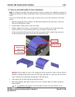
Page 68: ...to the up front cover The top cover is fixed with four screws the up front cover together with the manual 3 way valve cover are fixed with eight screws and the front cover is fixed with four screws Wa...

Page 69: ...tighten them but screw them half way 10 Press the four angles of the head plate with your hands to make it touch the platen completely 11 Tighten screws on each side of the carriage by turns tighten...

Page 70: ...each card into corresponding ejector header firmly then lock it with the header s two ears Printhead will be burned if the cards are not well plugged INKCUPS NOW SERIES INKJET PRINTERS XJET All right...

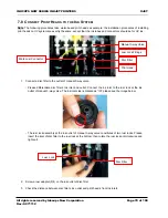
Page 71: ...valve The ink inlet side is marked as IN please see the image below The luer lock assembly at the ink outlet of manual 3 way valve constitutes of two luer locks Please insert the inlet of disc filter...

Page 72: ...djust the handle position of manual three way valve of one ink channel so that the print head is connected with flushing fluid Please check the section 3 2 for detailed information of using manual 3 w...

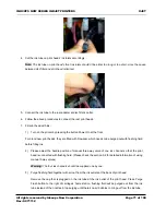
Page 73: ...ink will be purged out from the ink tube instead of the nozzles Stop purging until there s no air bubbles coming out from the ink tube Note Purge ink for 2 3 seconds air in the head will be purged ou...

Page 74: ...elp you do the alignment including step calibration step pass calibration vertical alignment and horizontal alignment Before that the mechanical alignment of the five heads should be done 7 9 1 CALIBR...

Page 75: ...f not rotate the Y adjustment screw of head K a little bit with a hex driver Clockwise rotation will push the head forward anti clockwise rotation will pull the head backward Note A magnifier 10X or h...

Page 76: ...Step Calibration dialogue pops up which shows the step value This dialogue is for you to check the step value click button Calibrate to do the calibration if you are not satisfied with the value and...

Page 77: ...pattern thoroughly find out the group in which the two rows of lines are best aligned For example in the following image group 0 is best aligned Enter the number below the group into the numeric box...

Page 78: ...est aligned group for each color may differ you need to select the group that most colors are best aligned For example in the chart above the best aligned group for all the colors in general is group...

Page 79: ...ertical alignment can help to make sure the all the printheads are well aligned in the vertical direction which means the first nozzles of all printheads are in one line Follow these steps to do the v...

Page 80: ...re again 3 Click the Calibration button to calibration the printheads if the test pattern in step 2 does not look good 4 Click the Print button the following test chart will be printed Enter the CMYK...

Page 81: ...Group1 M is 4 A and the best aligned group number in the test chart printed in step 4 is 1 B then you should update the Group 1 M value from 4 A to 5 A B 5 Press button Apply to save the calibration a...

Page 82: ...ould be made when feeding this type of media Follow the steps below to do the calibration 1 Select Step Pass Calibration from the Adjust Menu the Step Calibration dialogue pops up which shows the step...

Page 83: ...o 20 Each group has two rows of lines Check the pattern through find out the group in which most colors are best aligned For example in the following image group 0 is best aligned 2 1 0 1 20 20 2 INKC...

Page 84: ...rint the test chart will be sent to the printer to print as a job automatically The following image will be printed 5 Check the test chart and select the best aligned group for example in the chart ab...

Page 85: ...om left to right If printed image looks blurred in uni directional printing you should consider doing a horizontal alignment to the print heads Bi direction alignment is also included in horizontal al...

Page 86: ...black lines and short lines of black dots by printhead K1 are printed at the same position They are used for contrast The groups of lines and lines of dots printed by the second and third printheads o...

Page 87: ...tance if the Value that is already in the M 2 if the reading from the printed pattern gives 1 as the best value then M 2 1 which gives M 1 7 Click the button Next in the bottom of the dialogue the Bi...

Page 88: ...n Adjust menu 10 Click the button Next in the bottom of the dialogue the End to Original Alignment dialogue shows up 11 Click the button Print the test pattern of End to Original Alignment which is th...

Page 89: ...lick the Print button to print the following test charts on each point 16 Check the test charts and find the best aligned groups enter the values into the numeric up and down boxes of the middle colum...

Page 90: ...before Carriage Movement including printing and Purge when Print Heads are Capped Capping plate and wiping plate move to origin positions 4 Before Printer Power off Wiping plate and wiping plate move...

Page 91: ...efore automatic capping That means print heads will be capped automatically after the printer is idle for a period of time Power On Clean When this option is being checked print head will be purged wi...

Page 92: ...g and Purge and Printer Power off 8 3 1 PRINTER INITIALIZATION When the printer is turned on it needs several seconds to initialize during which the PWC module will operate automatically to purge ink...

Page 93: ...When Power On Clean is not checked INKCUPS NOW SERIES INKJET PRINTERS XJET All rights reserved by Inkcups Now Corporation Rev SC71112 Page 92 of 100...

Page 94: ...ipe the heads automatically Click the Auto Clean button on PCS Start End Switch 3 way E valve so that sub tanks are connected to ink pumps Purge ink purge time can be set on PCS Wiping plate moves to...

Page 95: ...ate and capping plate will move to get the carriage ready Start Capping plate moves down to the lowest position Carriage moves out Wiping plate moves to the origin Carriage moves to origin Carriage mo...

Page 96: ...e carriage will go back to the home station and the PWC will cap the heads Warning Before turning off the printer please switch manual three way valves position so that either the ink channels or flus...

Page 97: ...d Analog Force Pull Push Gauge 1 Assemble the Belt Pull Clamp at the Analog Pull Force Gauge please install the belt pull clamp 2 Check the initial tension of the Carriage Belt at the center of the Be...

Page 98: ...below Adjusting Method Tightening the two adjustment screws to move the belt pulley rightward so as to tighten the belt loosening the two adjustment screws to loosen the belt If the value is larger t...

Page 99: ...t Conveyor rolls for one cycle to clear printouts from printing platen Yes Is it the last template Yes Is the template at the top position Move tooling template down End No Move tooling template down...

Page 100: ...ey up stop move Up key Move it forward Down key Move it backward Enter key Exit this menu Menu key Return Status UI Set Load Device Postion Jog Capture Ink Supply Setup Supply Mode Manual Auto Pump Ti...

Page 101: ...nt Spit Sound Start Move Alarm Type Sound Light Sensor Switch Main Tank Waste Tank Z Height Protect Sensor White ink circulation pump Diagnose Negative System Start Motion General Check Aging About Pr...

Reviews: