Power Distribution Board (PDB) DRAFT
Code No. MD04001-00-1307
4
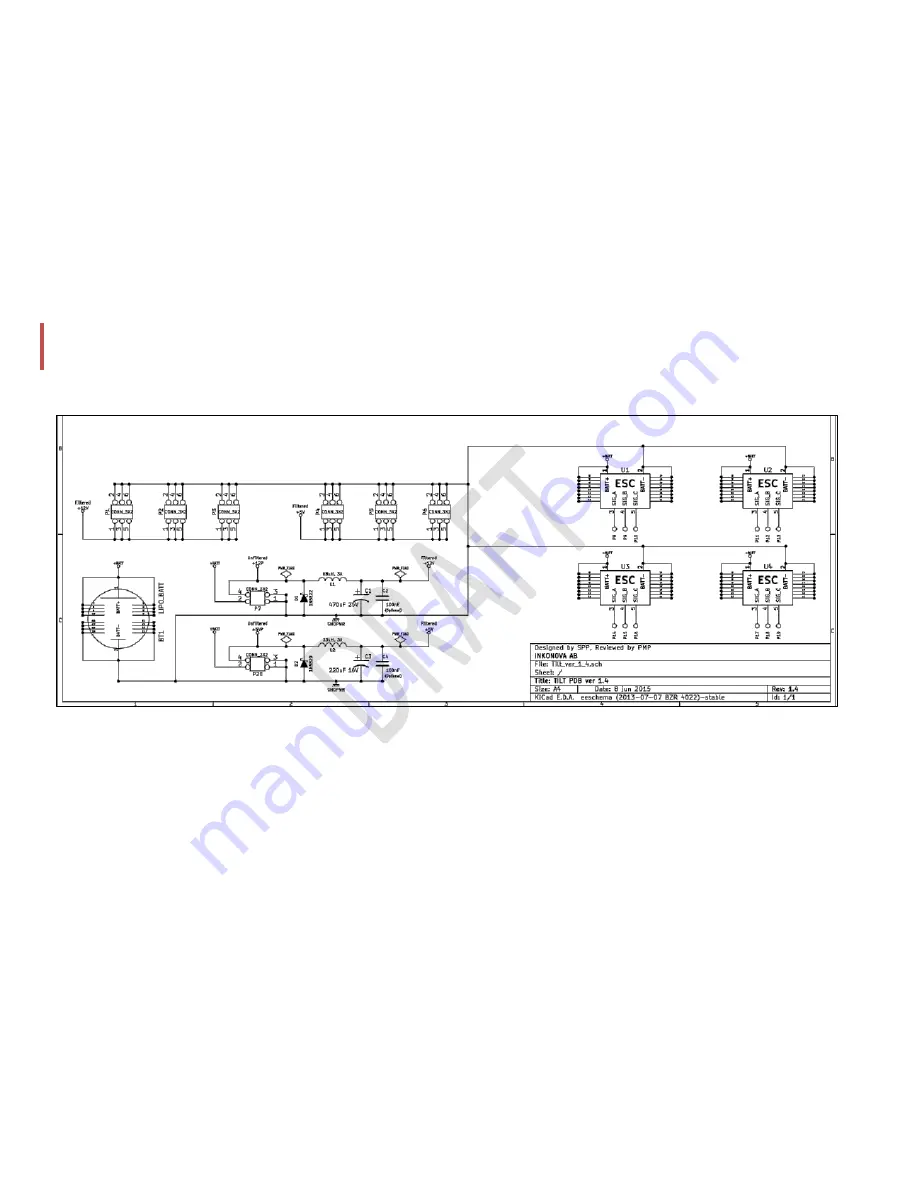
Circuit and notes
The PWR_FLAG (power flag) in the schematic below denotes the type of electrical connection on the power terminal and is not a
component used in the circuit.
The filter circuit used is a standard LM2596 filtering circuit. If you wish to use a different regulator to ge5V and +12V, you can
do it.
An additional 100nF capacitor is also provided for high frequency noise reduction in the circuit but do not solder it yet:
the small capacitor that both filter sets include are not usually necessary, test without them first if your FPV camera gets white
lines when the motors are spinning. If you see lines, install the small cap in the line (5 or 12 V) where you have the camera
connected (or the vtx line if the camera is powered by the vtx). Then, rotate the Naze so that the USB port is NOT in the same
side of the small cap you used: we found out that this small cap is exactly in the way of the USB port. Good news are that, as
Summary of Contents for MD04001-00-1307 DRAFT
Page 7: ...Power Distribution Board PDB DRAFT Code No MD04001 00 1307 8 IMAGES TO USE soldering steps...
Page 8: ...Power Distribution Board PDB DRAFT Code No MD04001 00 1307 9...
Page 9: ...Power Distribution Board PDB DRAFT Code No MD04001 00 1307 10...
Page 11: ...Power Distribution Board PDB DRAFT Code No MD04001 00 1307 12...
Page 12: ...Power Distribution Board PDB DRAFT Code No MD04001 00 1307 13...
Page 13: ...Power Distribution Board PDB DRAFT Code No MD04001 00 1307 14...
Page 14: ...Power Distribution Board PDB DRAFT Code No MD04001 00 1307 15...
Page 15: ...Power Distribution Board PDB DRAFT Code No MD04001 00 1307 16...
Page 16: ...Power Distribution Board PDB DRAFT Code No MD04001 00 1307 17...
Page 17: ...Power Distribution Board PDB DRAFT Code No MD04001 00 1307 18...
Page 18: ...Power Distribution Board PDB DRAFT Code No MD04001 00 1307 19...


