2
IN3526 OPERATION MANUAL - REV. 1 11/11/96 ©1996 - INLINE, INC.
DESCRIPTION
The
IN3526
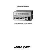
is a six input and one output switcher designed for composite or S-Video signals. The
IN3526
switcher is designed to route several video source signals to an attached video recorder, monitor, projector or
other video equipment. Users may select the desired input channel using front panel buttons or via remote
control. The
IN3526
switcher offers easy operation and the following features:
♦
100 MHz Bandwidth - allows the unit to be used with high resolution computer video signals as well as
NTSC/PAL/SECAM composite and S-Video signals
♦
Front Panel Channel Selection Controls and LED Indicators
♦
Contact Closure and RS-232 control port for remote selection of input channels
♦
Cascading capability to create larger switching configurations.
♦
I/O port to power and control an
IN3546
6 in, 1 out Stereo Audio Switcher for audio follow video
applications
COMPATIBILITY
The
IN3526
switcher will switch a wide variety of signals. While the unit was primarily designed for Composite
Video and S-Video (Y/C) signals, it can also switch high resolution computer video signals. The
IN3526
shares
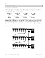
the composite video and Luma (Y) channel, so it is not designed to handle both signal formats at the same time.
However, if your display device can switch between composite and S-Video, you can have some inputs be
composite and others be S-Video (although you will need to switch your display to view the proper signal.)
INSTALLATION
This section offers step-by-step instructions for installing an
IN3526
switcher.
1. Connect all sources to the
IN3526
input connectors. Unused inputs do not need to be terminated.
2. Connect the
IN3526
output to the display device.
3. Connect remote control system if required.
4. Apply AC power to the unit.
5. Configure the unit for special applications (see Power-On Settings for more information.)

