IN3546R OPERATION MANUAL - REV. 2.1 12/01/98
©1998 - INLINE, INC.
2
INSTALLATION
The
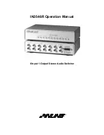
IN3546R
rear panel connections are shown in the diagram above.
1.
Connect the audio signals from each source to the INPUT connectors (labeled 1 - 6)
as required.
2.
Connect the
IN3546R
OUTPUT to the input of the next device in the audio system (mixer or
amplifier).
3.
Finally, connect the
IN9112
or
IN9133
15 pin control cable between the control port on the
IN3546R
and the
IN3500 / IN3600
Series
RGB switcher contact closure port. This provides
power to the
IN3546R
and a control link, triggered by the RGB switcher's tally outputs. The
IN3546R
will power up along with the
IN3500 /IN3600
series switcher to which it is linked.
Consult the
IN3500 / IN3600
Series manuals for more information about their tally output functions.
USING THE IN3546R IN STAND-ALONE CONFIGURATION
Some applications may require the
IN3546R
to be used as a stand-alone stereo audio switcher. Since the
IN3546R
normally receives power and switching commands from the attached RGB switcher, the
following procedure must be followed in order to use the
IN3546R
in a stand-alone configuration.
1.
The IN3546R must be special ordered for stand alone operation.
INLINE will make
factory modifications to allow for stand alone operation, which includes the addition of
jumper J8. When J8 is closed the unit is set for 9V or 12V power input on pin 8. The unit
cannot be used in conjunction with an
IN3500 / IN3600 Series
switcher when J8 is closed or
damage may occur.
2.
Power -
The installer must construct a special power/control cable according to the pin out
information on page
5. The installer must also provide a 9 volt 300 mA (min.) power source
to power the unit. The power from the 9V supply is applied to pin #8 on the IN3546R control
port. The unit contains an internal 9V to 5V power transformer.
Do not apply any voltage
to pin #9.
Switching -
In order to select different channels, a control device must be wired to provide
latching contact closure between the ground pin (#7) and the appropriate channel selection
pins.
Example:
In order to select input #2, provide a latching contact closure between pin
#14 and pin #7.


