Installation and Safety Instructions
For Models without a Power Switch:
The socket outlet shall be installed near the equipment and shall be accessible.
For Models with 110 / 220V Power Selector:
Caution: Before applying power to this unit, the voltage selector must be set to the appropriate setting to match local A/C line
voltage. Improper setting of the voltage selector may cause damage to the unit and create a potential fire hazard.
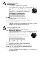
The voltage selector is a round switch located next to the A/C power input connector which looks
like this:
Using a straight slot screwdriver or small coin, rotate the selector to the correct position so that
the arrow lines up with 110 or 220 as appropriate for local power line voltage as indicated in the
chart below:
Local A/C Voltage
Voltage Selector Setting
110 ~ 120 VAC
110
220 ~ 240 VAC
220
For all Models:
No serviceable parts inside the unit. Refer service to a qualified technician.
For Models with Internal or External Fuses:
For continued protection against fire hazard, replace only with same type and rating of fuse.
For IN2001 / IN3234 / IN3236 / IN3502 / IN3504 / IN3506 / IN3562 / IN3564 / IN3566 / IN3572 / IN3574 / IN3576:
Caution: Double pole / neutral fusing.
For all Models with Integral Lithium Battery:
Caution: Danger of explosion if battery is incorrectly replaced. Replace only with the same or equivalent type recommended by
the manufacturer. Dispose of used batteries according to the manufacturer’s instructions.
Instructions d’installation et de sécurité
Pour les modèles sans interrupteur de courant:
La prise de courant d’alimentation sera installé près de l’équipement et sera accessible.
Pour les modèles avec un sélecteur d’alimentation 110V/220V:
Attention: Avant de connecter l’appareil au circuit d’alimentation, le sélecteur de courant doit être positionné sur la sélection
appropriée correspondant au voltage du circuit de courant alternatif local. Une mauvaise sélection peut engendrer des
dommages à l’appareil et créer un danger d’incendie.
Le sélecteur d’alimentation est un commutateur rond positionné près du connecteur
d’alimentation. Il se représente comme suit:
A l’aide d’un tourne-vis plat ou d’une pièce de monnaie, le sélecteur peut être tourné dans la
position adéquate en veillaut que la flèche corresponde avec 110 ou 220, en fonction de la
valeur du circuit de courant local. (Voir tableau ci-dessous)
Circuit local AC
Position Sélecteur
110 ~ 120 VAC
110
220 ~ 240 VAC
220
Pour tout les modèles:
Pas de composants à entretenir à l’intérieur. Confiez toute réparation à un technicien qualifié.
Pour les modèles équipés de fusibles internes ou externes:
Afin d’éviter tout danger d’incendie, ne remplacer qu’avec le même type et la même valeur de fusible.
Pour IN2001 / IN3234 / IN3236 / IN3502 / IN3504 / IN3506 / IN3562 / IN3564 / IN3566 / IN3572 / IN3574 / IN3576:
Attention: Double pôle / fusible au neutre.
Pour tout les modèles avec une batterie au lithium interne:
Attention: Danger d’explosion si la batterie est incorrectement remplacée. Ne remplacez la batterie qu’avec le même modèle,
ou avec un modèle recommandé par le constructeur. Traitez les batteries usagées selon les instructions du fabricant, ou selon
les normes écologiques en viguer.


