How to use on board Flash disk
31
5. How to use on board Flash disk
5.1 About solid state disk
The PI-6582 provides on-board 1.7MB flash ROM disk and one extended solid state disk
sockets (M1) which can accept EPROM/SRAM/FLASH. And also DiskOnChip
device
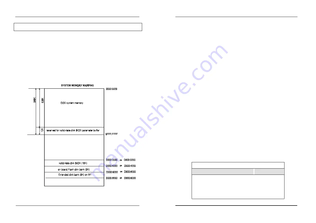
The PI-6582 solid state disk occupies two system memory sections.
Section 1
:the last 12K bytes at higher memory address for solid state
disk BIOS parameter buffer
Section 2
:Disk bank(32K) at D000:0000-D000:7FFFH or D800:0000-D800:7FFFH
(16K disk BIOS+16K disk bank)
How to use on board Flash disk
32
5.2 On board Flash disk hardware settings
There is a jumper called “JP13” should be set properly before using ROM/RAM disk. (refer
to chapter 2)
!"
JP13 pin 1-2 is used to set base port of disk
!"
JP13 pin 5-6 and pin 9-10 are used to enable or disable disk
!"
JP13 pin 3-4 is used to set the memory address occupied by disk
!"
JP13 pin 7-8 is used to set device type inserted on the socket “M1”
5.3 Solid state disk Setup
The solid state disk SETUP configures the solid state disk information that is stored in
EEPROM. The solid state disk has a window Setup interface that is recognizable to
anyone.
This setup function is available for on-board 1.7MB Flash and extended disk (M1 socket)
configuration
As Award BIOS POST executes, the following appears:
.
.
.WAIT……..
Hit <F10> to Run Advanced Solid state disk SETUP
At this time, Hit <F10> to run Solid state disk SETUP. A SETUP window shows up on the
screen.
.
All-in-one 80386SX CPU Card ROM/RAM Disk SetUp Vx.x
Primary disk drive
:A
Secondary disk drive
None
System boot sequence
:Flash disk
COM port for remote Flash PGM
:COM1
Auto detect and boot from Disk A:
:Disabled
PgUp/PgDn:Select - Esc:No save - F7:Save


