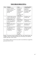
background image

17 


TROUBLESHOOTING 


Item 

Problem 

Cause 

Action Required 

Red LED flashing 
quickly (every 0.2 sec.) 
when any motion 
pushbutton is 
pressed. 

a) One of the 
pushbutton 
is jammed. 
b) The system is 
not properly 
powered 
according to the 
instructions. 

a) Replace the 
Pushbutton. 
b) Power on again 
according to the 
instructions. 

TX LED flashes red and 
yellow reciprocally and 
slowly (every 0.5 sec.) 

The memory of 
the TX is 
defective. 

Send back to the 
manufacturer. 

TX LED flashes red 
every 2 sec., when any 
motion pushbutton is 
pressed. 

The transmitter 
batteries are at 
low power. 

Replace the 2 AA 
size Alkaline 

Batteries at once. 

RX Error LED flashes 
red slowly (every 
0.5sec.) 

The memory of 
the RX is 
defective. 

Send back to the 
Manufacturer. 

The operating distance 
is shorter or an 
intermittent operation 
is happening. 

It was interfered 
by other 
Radio Remote 
Controller 
/or unknown 
signal with 
the same 
frequency. 

Replace the crystal 
of both TX and RX 
to change the 
frequency. 

Remark: The memory of the TX and RX has Anti-copy function design, any 
inadequate action on decoding the firmware of the memory will cause the 
trouble as the above items 2 and 4. 
 
If any problem cannot be solved or if you have any comments or suggestions 
please call 888-501-2220. 


Summary of Contents for 140 Series

Page 1: ......

Page 2: ...be returned to our factory Customer is responsible for shipping charges to INMOTION Controls Inc while INMOTION Controls Inc will pay return shipping charges This warranty does NOT include consumable parts such as joystick batteries fuses buttons and relays or damage from normal wear and tear Furthermore this warranty does NOT cover defects caused by misuse neglect accident failure to follow instr...

Page 3: ... off main power in Crane and the power to Receiver Transmitter should be placed safely when not in use to avoid accidental pressing of buttons The Crane should be equipped with main power Relay Limit Switch and other required safety devices The GND ground of Receiver must be connected with metal part of Crane or electrical shock will occur Do not use this device during electrical storm or high ele...

Page 4: ...mote Control operator must have adequate training and related license to avoid danger Series 140 160 180 Transmitter is durable and weather resistant but care should be taken not to subject it to severe impact or pressure Series 140 160 180 is suitable for use in diverse industrial environments and adequate operating and maintenance will extend system s life Check EMS mushroom and the other securi...

Page 5: ... please follow the steps below and ask the distributor for service immediately Press the Stop pushbutton Remove the batteries Shut off the main power of the Crane and discontinue the operation Contact the distributor to find out possible causes ...

Page 6: ...5 STANDARD ACCESSORIES A standard INMOTION Series 140 160 180 System consists of 1 Transmitter 2 units 2 Receiver 1 unit Note INMOTION Series 180 shown ...

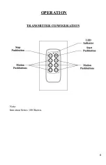
Page 7: ...6 OPERATION TRANSMITTER CONFIGURATION Note Inmotion Series 180 Shown ...

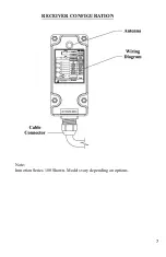
Page 8: ...7 RECEIVER CONFIGURATION Note Inmotion Series 180 Shown Models vary depending on options ...

Page 9: ...ion perform the following procedures in sequence 1 Press the Stop pushbutton 2 Keep the transmitter in a safe place 3 Switch main power off to the equipment Crane 4 Remove batteries if not used for a long period of time Note Transmitter has power indicating functions with LED display Green Color The LED will flash green when battery power is sufficient Red Color The LED will flash red when the pow...

Page 10: ...0A 36 VDC 2 AC Type Three different AC transformers 24 48V 48 110V 110 220V Set the jumper to either Hi or Lo depending on which voltage is required See the chart and diagram below LO HI AC24 48 Transformer 24 48 AC48 110 Transformer 48 110 AC110 220 Transformer 110 220 Note Standard Systems are 48 110 VAC If any others are required please specify when ordering ...

Page 11: ...10 DC TYPE RELAY P C BOARD LAYOUT For INMOTION 140 160 180 Note The Polarity of DC Input is not requried when plugging in the power ...

Page 12: ...11 AC TYPE RELAY P C BOARD LAYOUT INMOTION 180 Shown Note The Ground of the receiver must be connected with metal Part of equipment or electrical shock may occur ...

Page 13: ...Down E W R0 INMOTION 140 2 Independent COM Lines Up Down R0 Please refer to the figure of the relay board above If any independent COM line is required then cut the wire labeled with a white X The longer part of the wire will become the new COM line Then you may connect this new COM wire with an existing spare output wire If no spares are available the customer must supply extra wire ...

Page 14: ...e LED will flash green when the battery power is sufficient The LED will flash red when the battery power is low The operating distance will become shorter and intermittent when the battery is low Replace with new battery when battery power is low DO NOT USE RECHARGEABLE BATTERIES ...

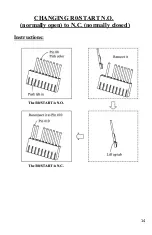
Page 15: ...14 CHANGING R0 START N O normally open to N C normally closed Instructions ...

Page 16: ...the power AC 48 110 220 is 0 25A The fuse for the power DC 12 24V is 1 5A 3 The fuse for the AC type at the COM MAIN is 10A The fuse for the DC type at the COM MAIN is 20A 4 The COM lines have been arranged prior to shipment If an independent COM line is required please refer to Page 14 ...

Page 17: ...16 NOTES ...

Page 18: ... The transmitter batteries are at low power Replace the 2 AA size Alkaline Batteries at once 4 RX Error LED flashes red slowly every 0 5sec The memory of the RX is defective Send back to the Manufacturer 5 The operating distance is shorter or an intermittent operation is happening It was interfered by other Radio Remote Controller or unknown signal with the same frequency Replace the crystal of bo...

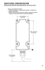
Page 19: ...18 MOUNTING THE RECEIVER Please note that the drawing below is not to scale ...

Page 20: ...19 ...

Reviews: