background image


17


3    Introduction to Web Configuration 

The first time you setup the Router. It is recommended that you configure the WAN 

connection using a single computer, to ensure that both the computer and the 

Router are not connected to the LAN. Once the WAN connection operates properly, 

you may continue to make changes to Router configuration, including IP settings 

and DHCP setup. This chapter is concerned with using your computer to configure 

the WAN connection. The following chapter describes the various menus used to 

configure and monitor the Router, including how to change IP settings and DHCP 

server setup. 

3.1    Preparation Before Login 

Before accessing the Modem, ensure the communication between PC and Modem 

is normal. Check the communication as follows. 

Configure the IP address of the PC as 192.168.1.X (2~254), net mask as 255. 

255.255.0,  gateway  address  as  192.  168.1.1  (for  customized  version, 

configure them according to the actual version). 

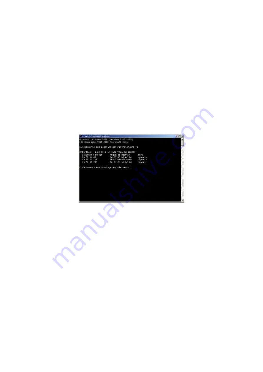
Enter 

arp -a

 in the DOS window to check whether the PC can read the MAC 

address of the Modem. 


Ping the management IP address (192.168.1.1 by default) of the Modem. 

Summary of Contents for W3100V

Page 1: ...W3100V One port ADSL 2 Wireless Router User Manual ...

Page 2: ...2 2 Connecting the ADSL Router 13 2 3 Factory Reset Button 13 3 Introduction to Web Configuration 17 3 1 Preparation Before Login 17 3 2 Logging In to the Modem 18 3 2 1 First Time Login 18 3 3 DSL Router Device Information 19 3 3 1 Summary of Device Information 19 3 3 2 WAN Interface Information 20 3 3 3 Statistics of LAN 21 3 3 4 Statistics of WAN 21 3 3 5 Statistics of ATM 22 3 3 6 Statistics o...

Page 3: ...eless Advanced 106 3 5 7 Wireless Authenticated Stations 109 3 6 Diagnostics 110 3 7 Management 111 3 7 1 Settings 111 3 7 2 System Log 113 3 7 3 TR 069 Client 115 3 7 4 Internet Time 116 3 7 5 Access Control 117 3 7 6 Update Software 119 3 7 7 Save Reboot 120 4 Networking Topology 121 4 1 PPP over ATM PPPoA Mode 121 4 2 PPP over Ethernet PPPoE Mode 123 4 3 MER DHCP Mode 124 4 4 IP over ATM IPoA N...

Page 4: ... Network WAN interface and single global IP address The advanced security enhancements packet filtering and port redirection can help protect your network from potentially devastating intrusions by malicious agents from outside your network Network and Router management is done through the web based management interface that can be accessed through the local Ethernet using any web browser You may ...

Page 5: ...guration file backup and restore Simple web based status page displays a snapshot of your system configuration and links to the configuration pages Support DHCP server client relay Support self learning bridge IEEE 802 1D Transparent Bridging Support 64 learning MAC addresses at least Support IP source and destination routing Support address Filtering UPnP NAT NAPT DMZ IP QoS Supporting up to 16 P...

Page 6: ...r wireless Industry standard and interoperable DSL interface 1 3 Wireless Specifications Item Description Network Standard IEEE 802 11b IEEE 802 11g Frequency Range 2 40 GHz 2 4835 GHz ISM Band Modulation 802 11b DBPSK DQPS CCK 802 11g BPSK QPSK 16QAM 64QAM RF Power 20 dBm Max 802 11bType 16 5 1 5 dBm Normal Temp Range 802 11gType 15 1 5 dBm Normal Temp Range Access User Quantity 50 Pcs 80 Pcs AP ...

Page 7: ...MAC Level MAC Filter Eth Interface MAC Filter Support Vacancy MAC Filter Support Authentication DHCP Client Static IP Support 802 1X and Radius Client Support DHCP Server Support Radio Cover Rage Outdoor 120m 400m Indoor 35m 100m Antenna Type Internal Diversity with Connector 2 dBi 1 4 Compliance Certificates FCC Class B CE Mark 1 5 Standards Compatibility and Compliance RFC 2684 multi protocol En...

Page 8: ...Ethernet over AAL5 Support ALG Application Level Gateways ITU G 992 1 G dmt ITU G 992 2 G lite ITU G 994 1 G hs ITU G 992 3 ADSL2 ITU G 992 5 ADSL2 ANSI T1 413 issue 2 IEEE802 3 IEEE802 3u IEEE 802 11b IEEE 802 11g 1 6 Supported Encapsulation RFC 1483 bridge RFC 1483 Router Classical IP over ATM RFC 1577 PPP over ATM RFC 2364 PPP over Ethernet RFC 2516 1 7 Environment Requirements Operating temper...

Page 9: ...tifier VPI is used in conjunction with the virtual channel identifier VCI to identify the data path between the network of your ADSL service provider and your computer If you set up the Router for multiple virtual connections you need to configure the VPI and VCI as instructed by your ADSL service provider for additional connections You can change this setting by accessing the WAN menu of the web ...

Page 10: ...PoA LLC and PPPoA VC MUX Other available connections and encapsulation combinations must be configured by using the Web manager These include the Bridge Mode 1483 Bridged IP LLC or 1483 Bridged IP VC MUX Static IP Bridged IP LLC 1483 Bridged IP VC MUX 1483 Routed IP LLC 1483 Routed IP VC MUX or IPoA etc Username This is the user name used to log in to the network of your ADSL service provider It i...

Page 11: ...sk used by the DSL Router and is used throughout your LAN The default subnet mask is 255 255 255 0 You can change it later Username This is the user name used to access the management interface of the gateway when you attempt to connect to the device through a web browser The default username of the Router is admin It cannot be changed Password This is the password required when you access the man...

Page 12: ...that is packed within the device package Pay attention to the power load of the outlet or prolonged lines An overburden power outlet or damaged lines and plugs may cause electric shock or fire accident Check the power cords regularly If you find any damage replace it at once Proper space left for heat radiation is necessary to avoid any damage caused by overheating to the device The holes are desi...

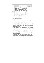
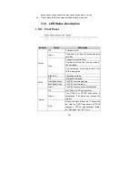
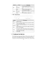
Page 13: ...boot loader Red The self testing of the power fails if the LED is always red Power Blink Red Upgrading software Off No signal is detected Slow Blink Green The DSL line is transferring Fast Blink Green The DSL line is training ADSL Green The DSL line connection is established Off No PPPoA or PPPoE connection Green The PPPoA or PPPoE connection is established The users can access the Internet Intern...

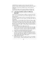
Page 14: ...the modem with the ADSL cable or splitter Ethernet RJ 45 port connect the modem to a PC or other network device PWR Power supplied port plug in for power adapter that the power input is 12V DC 800m A Reset To restore the factory default keep the device powered on and push a needle into the hole Press down the button about 3 seconds and then release Power switch 2 Hardware Installation The DSL Rout...

Page 15: ... However the numbers of walls ceilings or other objects that the wireless signals must pass through limit signal range Typical ranges vary depending on types of materials and background RF noise in your home or business For optimum range and signal strength use these basic guidelines Keep the numbers of walls and ceilings to the minimum The signal emitted from wireless LAN devices can penetrate th...

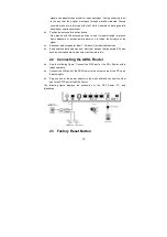
Page 16: ... of the signal Keep your product away at least 1 2 meters from electrical devices Keep wireless devices away from electrical devices that generate RF noise such as microwave ovens monitors electric motors etc 2 2 Connecting the ADSL Router See the following figure Connect the DSL port of the DSL Router with a telephone cable Connect the LAN port of the DSL Router to the network card of the PC via ...

Page 17: ...oint or paperclip to gently push down the reset button Remember that this wipes out any settings stored in the flash memory including user account information and LAN IP settings The device settings are restored to the following factory defaults the IP address is 192 168 1 1 subnet mask is 255 255 255 0 user name for management is admin and password is admin ...

Page 18: ...nection The following chapter describes the various menus used to configure and monitor the Router including how to change IP settings and DHCP server setup 3 1 Preparation Before Login Before accessing the Modem ensure the communication between PC and Modem is normal Check the communication as follows Configure the IP address of the PC as 192 168 1 X 2 254 net mask as 255 255 255 0 gateway addres...

Page 19: ...o the DSL Router for the first time the login wizard appears Step 1 Open a Web browser on your computer Step 2 Enter http 192 168 1 1 DSL router default IP address in the address bar The login page appears Step 3 Enter a user name and the password The default username and password of the super user are admin and admin The username and password of the common user are user and user You need not ente...

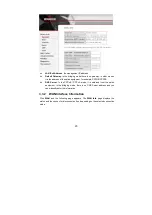
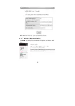
Page 20: ...uration effective in some cases for example after you modify the PVC configuration Some modification such as adding a static route takes effect at once and does not require modem reboot 3 3 DSL Router Device Information Click Device Info and you can view the following information Summary WAN Statistics Route ARP DHCP 3 3 1 Summary of Device Information Click Summary and the following interface app...

Page 21: ... PPPOE PPPOA DNS Server In the PPPoE PPPoA mode it is obtained from the uplink equipment In the bridging mode there is no DNS Server address and you can manually enter the information 3 3 2 WAN Interface Information Click WAN and the following page appears The WAN Info page displays the status and the connect or disconnect button depending on the selected connection mode ...

Page 22: ...d at the Ethernet and wireless interfaces Click Reset Statistics to restore the values to zero and recount them 3 3 4 Statistics of WAN Click Statistics WAN and the following page appears You can query information of packets recevied at the WAN interfaces Click Reset Statistics to restore the values to zero and recount them ...

Page 23: ...e appears You can query information of packets recevied at the ATM interfaces Click Reset to restore the values to zero and recount them 3 3 6 Statistics of ADSL Click Statistics ADSL and the following page appears If the DSL line is activated the window shows as follows ...

Page 24: ...23 Click Reset Statistics at the bottom to restore the values to zero and recount them ...

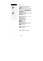
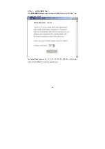
Page 25: ...st Click ADSL BER Test to perform a bit error rate BER test on the DSL line The test page is as follows The Tested Time sec can be 1 5 10 20 60 120 180 240 300 or 360 Select a time and click Start The following pages appear ...

Page 26: ...25 ...

Page 27: ...26 Note If the BER reaches e 5 you cannot access the Internet 3 3 7 Route Table Information Click Route and if the system is in the default configuration the following page appears ...

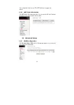
Page 28: ...Table Information Click ARP and the following page appears You can query the MAC and IP address information of the equipment attached to the modem 3 4 Advanced Setup 3 4 1 WAN Configuration Click Advanced Setup WAN and the following page appears so you can modify and configure the WAN interface ...

Page 29: ...ervice categories and QoS VPI Virtual path between two points in an ATM network Its valid value range is from 0 to 255 VCI Virtual channel between two points in an ATM network Its valid value range is from 32 to 65535 1 to 31 are reserved for known protocols Service Category UBR Without PCR UBR With PCR CBR Non Realtime VBR Realtime VBR Enable Quality Of Service Enable or disable QoS In this examp...

Page 30: ... to LLC SNAP BRIDGING according to the uplink equipment Enable the 802 1q VLAN tag value Note that 802 1q VLAN tagging is only available for PPPoE MER and Bridge Click Next and the following page appears Step 3 In this page you can modify the PPP user name PPP password authentication method and so on ...

Page 31: ...modem automatically stops the PPPOE connection Once it detects the flow like access to a webpage the modem restarts the PPPOE dialup If this function is disabled the modem performs PPPOE dial up all the time The PPPOE connnection does not stop unless the modem is powered off and DSLAM or uplink equipment is abnormal PPP IP extension If this function is enabled the WAN IP address obtained by the mo...

Page 32: ...word click Next and the following page appears In this page you can modify the service name and enable or disable the IGMP multicast and WAN service Enable IGMP Multicast IGMP proxy For example if you wish that the PPPoE mode supports IPTV enable this function Enable WAN Service Enable it unless you do not want to active the PVC Click Next and the following page appears This page shows all the con...

Page 33: ...ettings click Save To make any modifications click Back After you click Save the following page appears Note You need to reboot the modem to activate this WAN interface and further configure services in this interface ...

Page 34: ...age you can modify VPI VCI service categories and QoS In this example PVC 8 35 is to be modified and the default values of service category remain In actual applications you can modify them as required After proper modifications click Next and the following page appears In this page you can modify the Internet Connection Type and Encapsulation Type ...

Page 35: ...VC 8 35 to PPP over ATM PPPoA and set the Encapsulation Mode to VC MUX according to the uplink equipment Click Next and the following page appears In this page you can modify the PPP Username PPP Password Authentication Method and so on ...

Page 36: ...35 After entering the PPP user name and password click Next and the following page appears In this page you can modify the service name and enable or disable the IGMP multicast and WAN service ...

Page 37: ...rewall enable To save the settings click Save To make any modifications click Back After you click Save the following page appears Note You need to reboot the modem to activate this WAN interface and further configure services in this interface 3 4 1 3 MER Configuration This section describes the procedure for adding PVC 8 35 MER mode ...

Page 38: ...vice category remain In actual applications you can modify them as required After proper modifications click Next and the following page appears In this page you can modify the Internet connection type and encapsulation type Change the connection type of PVC 8 35 to MAC Encapsulation Routing MER and set the Encapsulation Mode to LLC SNAP BRIDGING according to the uplink equipment ...

Page 39: ...38 Click Next and the following page appears In this page you can modify the WAN IP address default gateway and DNS server settings ...

Page 40: ...ISP WAN Subnet Mask Enter the subnet mask concerned to the IP address of the WAN interface provided by your ISP Obtain default gateway automatically Obtain the IP address of the default gateway assigned by the uplink equipment such as BAS Use the following default gateway If you want to manually enter the IP address of the default gateway select this check box and enter the information in the fiel...

Page 41: ...s page you can modify the service name and enable or disable the NAT firewall IGMP multicast and WAN service Enable NAT Select it to enable the NAT functions of the modem If you do not want to enable NAT and wish the modem user to access the Internet normally you must add a route on the uplink equipment Otherwise the access to the Internet fails It is normal to enable NAT Enable Firewall Enable or...

Page 42: ...hows all the configuration To save the settings click Save To make any modifications click Back After you click Save the following page appears Note You need to reboot the modem to activate this WAN interface and further configure services in this interface ...

Page 43: ...C 8 35 is to be modified and the default values of service category remain In actual applications you can modify them as required After proper modifications click Next and the following page appears In this page you can modify the Internet connection type and encapsulation type Change the connection type of PVC 8 35 to IP over ATM IPoA and set the Encapsulation Mode to LLC SNAP ROUTING according t...

Page 44: ...43 Click Next and the following page appears In this page you can modify the WAN IP default gateway and DNS server settings ...

Page 45: ...provided by your ISP Use WAN Interface As to BAS equipment it is the IP address of the downlink interface Use the following DNS server addesses If you want to manually enter the IP address of the DNS server select this check box and enter the information in the fields Primary DNS server Enter the IP address of the primary DNS server Secondary DNS server Enter the IP address of the secondary DNS se...

Page 46: ...equipment Otherwise the access to the Internet fails Normally NAT should be enabled Enable Firewall Enable or disable IP filtering Enable IGMP Multicast IGMP proxy For example if you wish that the IPoA mode supports IPTV enable this function Enable WAN Service Enable it unless you do not want to active the PVC Click Next and the following page appears This page shows all the configuration ...

Page 47: ...s Note You need to reboot to the modem to activate this WAN interface and further configure services in this interface 3 4 1 5 Bridge Configuration This section describes the procedure for adding PVC 8 35 IPoA mode Click Add and the following page appears In this page you can modify VPI VCIs service categories and QoS ...

Page 48: ... the default values of service category remain In actual applications you can modify them as required After proper modifications click Next and the following page appears In this page you can modify the Internet connection type and encapsulation type ...

Page 49: ...48 Click Next and the following page appears In this page you can modify the service name ...

Page 50: ...he following page appears This page shows all the configuration To save the settings click Save To make any modifications click Back After you click Save the following page appears Note You need to reboot the modem to activate this WAN interface and further configure services in this interface ...

Page 51: ...n In this interface you can modify and configure IP Address and DHCP Server If the mode is bridge the interface shows as below Enable IGMP Snooping It is used to Bridge mode If the mode is router the interface shows as follows ...

Page 52: ... TCP or UDP If an external application tries to send a call to a PC in the local network the router blocks it There is no open port via which the data could enter the local network Some applications such as games on the Internet require several links that is several ports so that players can communicate with each other In addition these applications must also be permitted to send requests from oth...

Page 53: ...ocal network are converted to the public IP address of the router when accessing the Internet You can use NAT settings to configure the DSL router to carry out the following tasks For functions described as follows IP addresses of the PCs must remain unchanged If the IP addresses of the PCs are assigned via the DHCP server of the DSL router you must disable DHCP server as the settings in the local...

Page 54: ...nt applications can be assigned to your LAN computers however each type of application is limited to use one computer For example you can define that FTP uses address X to reach computer A and Telnet also uses address X to reach computer A But attempting to define FTP to use address X to reach both computer A and B fails DSL router therefore provides the ability to add additional public IP address...

Page 55: ...ociated with these applications contain information that allows them to be routed correctly An ALG is needed to handle these packets and ensure that they reach their intended destinations DSL router is equipped with a robust list of ALG modules in order to enable maximum functionality in the home network The ALG is automatically assigned based on the destination port Virtual servers are configured...

Page 56: ...r can be assigned to provide a specific service or application Step 5 Set External Port Start and External Port End Step 6 Select Protocol Step 7 Set Internal Port Start and Internal Port End Step 8 Enter Remote IP Step 9 Click Save apply to apply the settings If the application you require is not in the list manually enter the information Select the protocol for the service you are providing from...

Page 57: ...t 80 on the Web server of the PC you have defined with port 8080 Deleting Port Forwarding Step 1 Select the Remove check box Step 2 Click Remove to apply the settings 3 4 3 3 Port Triggering If you configure port triggering for a certain application you need to determine a so called trigger port and the protocol TCP or UDP that this port uses You then assign the public ports that are to be opened ...

Page 58: ...the protocol that is to be monitored for outgoing data traffic Open Protocol select the protocol that is to be allowed for incoming data traffic Open Port Start and Open Port End enter the port that is to be opened for incoming traffic Step 3 Click Save Apply to apply the settings Removing Port Triggering Step 1 Select the Remove check box Step 2 Click Save Apply to apply the settings 3 4 3 4 DMZ ...

Page 59: ...ou can set up a client in your local network as a so called DMZ host Your device then forwards all incoming data traffic from the Internet to this client You can for example operate your own Web server on one of the clients in your local network and make it accessible to Internet users As the exposed host the local client is directly visible to the Internet and therefore particularly vulnerable to...

Page 60: ...e following interface appears By default the firewall is enabled The firewall is used to block document transmissions between the Internet and your PC It serves as a safety guard and permits only authorized documents to be sent to the LAN Note If the modem is configured to bridge mode only IP filtering is disabled and the IP filtering interface does not appear If the modem does not configure a PVC...

Page 61: ...ic can be blocked by setting up filters Click Add and the page for defining the IP filtering rule appears In this page you can create a filter rule to identify outgoing IP traffic by specifying a new filter name and at least one condition All specified conditions in the filtering rule must be complied with the rule to take effect Click Save Apply to save and activate the filter ...

Page 62: ...61 For example if you need to block a PC whoese IP address is 192 168 1 10 All outgoing IP traffic from that PC 192 168 1 10 is disallowed The confiuration is as follows ...

Page 63: ...all is enabled However some IP traffic can be accepted by setting up filters Click Add the following page appears In this page you can create a filter rule to identify incoming IP traffic by specifying a new filter name and at least one condition All specified conditions in this filter rule must comply with the rule Click Save Apply to save and activate the filter You should select at least one WA...

Page 64: ...ly effective on ATM PVCs configured in Bridge mode Forwarded means that all MAC layer frames are forwarded except those matching with any of the specified rules in the following table Blocked means that all MAC layer frames are blocked except those matching with any of the specified rules in the following table ...

Page 65: ...ORWARDED to BLOCKED Read the warning information Click Yes to change the MAC filtering global policy from Forwarded to Blocked Click No to cancel For example to forbid the PC whose MAC address is 00 13 20 9E 0F 10 through PPPoE dial up begin with the following page Click Add to configure the interface as follows ...

Page 66: ...65 Click Save Apply and the following page appears 3 4 5 Parental Control Click Security Parental Control and the following page appears ...

Page 67: ...ing To restrict other LAN device click Other MAC Address and enter the MAC address of the another LAN device To obtain the MAC address of a Windows based PC enter ipconfig all in the DoS window 3 4 6 Quality of Service Many communication and multimedia applications require large high speed bandwidths to transfer data between the local network and the internet However for many applications there is...

Page 68: ...k traffic was treated equally The result was that all network traffic received the network s best effort with no guarantees for reliability delay variation in delay or other performance characteristics With best effort delivery service however a single bandwidth intensive application can result in poor or unacceptable performance for all applications The QoS concept of quality is one in which the ...

Page 69: ...r bridging not under control of the packet QoS Click Queue Config and the following page appears In this page you can configure QoS queue A maximum of 24 entries can be configured QoS Queue Configuration can allocate four queues Each of the queues can be configured for a precedence value Lower integer values for precedence imply higher priority for this queue relative to others The queue entry con...

Page 70: ...r disable a QoS queue Queue select a specific network interface When you have already selected a network interface the specific network interface selected automatically allocates to the queue Queue Precedence select an integer value for queue precedence After you select an integer value the queue entry appropriately places to ingress packets Lower integer values for precedence imply higher priorit...

Page 71: ... click Remove After the queue is configured you can create several traffic class rules to classify the upstream traffic WRR Weighted Round Robin this is another QoS method If you want to set WRR you must disable the Strict Priority Queue PQ The WRR is mutex to PQ Only one QoS method can exist at the same time Select WRR in QoS Queue Configuration page The following interface appears ...

Page 72: ...and weight value to 30 After proper modifications click Save Apply and the following page appears The weighted round robin WRR queue schedule divides each port into several output queues Queues are scheduled in turn to ensure that each queue obtains a certain service time WRR configures a weighted value w3 w2 w1 and w0 for ...

Page 73: ...time slice if a certain queue is null it is immediately changed to the next queue In this way the bandwidth resources can be fully utilized 3 4 6 3 QoS QoS Classification Some applications require specific bandwidth to ensure its data be forwarded in time QoS classification can creates traffic class rule to classify the upstream traffic Assign queue which defines the precedence and the interface a...

Page 74: ... the following page appears Traffic Class Name Enter a name of the class Rule Order Select order for queue Rule Status Enable or disable this traffic class rule Assign Classification Queue Select a classification queue ...

Page 75: ...TCP UDP or ICMP protocols Source IP Address Source subnet mask UPD TCP Source Port Destination IP Address Destination Subnet Mask UPD TCP destination port or a range of ports Source Mac Address Source Mac Mask Destination Mac Address Destination Mac Mask Set 2 Rules contain the following 802 1p Priority the 802 1p header includes a 3 bit prioritization field which allows packets to be grouped into...

Page 76: ...itted packet with an appropriate DSCP The DSCP markings are used by Diffserv network routers to appropriately classify packets and to apply particular queue handing or scheduling behavior Layer 3 IPV4 packet Versi on le ngth TOS 1 word leng th I D Offs et mar k T T L protoc ol Chec k sum IP S A IP DA d a t a TOS filed IP priority TOS front 3 bit or DSCP front 6 bit 7 6 5 4 3 2 1 0 IP priority Unde...

Page 77: ...c is simply classified and sent to the destination with no bandwidth reservations established The follow diagram shows the structure of 802 1Q Frame The 802 1Q header includes a 3 bit prioritization field which allows packets to be grouped to be grouped into eight levels of priority 0 7 where level 7 is the highest one In addition DSL maps these eight levels to priority queues where queue 1 has th...

Page 78: ...word Mark TPID 0x8100 Priority 3bit CFI 1bit VLAN ID 12bit For example mark the frame of 802 1p that queued to Queue 9 on value 2 After proper modifications click Save Apply to show the following interface ...

Page 79: ...n this page you can modify the default gateway settings If you select Enable Automatic Assigned Default Gateway this router can accept the first received default gateway assignment from one of the PPPoA PPPoE or MER DHCP enabled PVC s If the check box is not selected you need to enter the static default gateway and or a WAN interface Then click Save Apply ...

Page 80: ...ay 3 4 7 2 Routing Static Route In this interface you can modify the static route settings In this interface you can query the preset static routes delete an existing static route or add a new static route By default the system has no static route information Destination The IP address to which packets are transmitted Subnetmask The subnet mask of the destination IP address ...

Page 81: ...pass by during transmission Interface The interface that the packets pass through on the modem Click Add and the following page appears To add a static route rule the configuration is as follows Click Save Apply and the following page appears ...

Page 82: ...DNS server settings If select Enable Automatic Assigned DNS this router accepts the first received DNS assignment from one of the PPPoA PPPoE or MER DHCP enabled PVC s during the connection establishment If the checkbox is not selected enter the primary and optional secondary DNS server IP addresses The interface is as follows ...

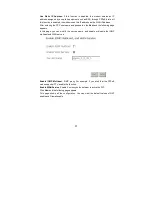
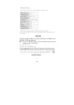
Page 83: ...ve 3 4 8 2 Dynamic DNS In this interface you can modify the Dynamic DNS settings The Dynamic DNS service allows you to alias a dynamic IP address to a static hostname in any of the many domains allowing your DSL router to be more easily accessed from various locations on the Internet Click Add to add dynamic DDNS ...

Page 84: ...this interface you can modify the DSL settings Select one you need But the default setting can check G dmt G lite T1 413 ADSL2 Annexl ADSL2 Inner pair Bitswap The modem can negotiate the modulation mode with the DSLAM ...

Page 85: ...84 3 4 10 IPSec Click IPSec and the following page appears Click Add New Connection to add a new IPSec connection ...

Page 86: ...ply to save this connection then you can check the checkbox of enable column to enable this IPSec connection And the communication is established 3 4 11 Certificate 3 4 11 1 Local Certificates Click Certificate Local and the following page appears Local certificates are used by peers to verify your identity It can store maximum 4 certificates ...

Page 87: ... certificate signing request you need to include Common Name Organization Name State Province Name and the 2 letter Country Code for the certificate If click Import Certificate the following page appears Then you can enter certificate name paste certificate content and private key ...

Page 88: ...87 3 4 11 2 Trusted CA Certificates Click Certificate Trusted CA and the following page appears CA certificates are used by you to verify certificates of peers It can store maximum 4 certificates ...

Page 89: ...ess This section introduces the wireless LAN and some basic configurations Wireless LAN can be as simple as two computers with wireless LAN cards communicating in a peer to peer network or as complex as a number of computers with wireless LAN cards communicating through access points AP that bridge network traffic to the wired LAN ...

Page 90: ...s All wireless client adapters compliant to 802 11g and or 802 11b can communicate with the Modem W LAN environment However be aware that only 802 11g compliant wireless clients are able to gain full profit of the 54 Mb s Max bandwidth delivered by the Modem It is highly recommended to use only wireless client adapters that are Wi Fi certified to ensure smooth interoperability with the Modem s WLA...

Page 91: ...ss the Router through the wireless interface Adding more 802 11g access points to rooms where the signal is weak can improve signal strength Read the section about placement of the Router titled Location in the next chapter Hardware Installation for more information 3 5 1 5 SSID Wireless networks use an SSID Service Set Identifier to allow wireless devices to roam within the range of the network W...

Page 92: ...nels USA Canada 1 to 11 3 5 1 7 Wireless Security Various security options are available on the Modem including open or WEP 802 1x WPA WPA PSK WPA2 and WPA2 PSK Authentication may use an open system or a shared key For details on these methods and how to use them please read the wireless LAN configuration information in Section 3 5 3 Wireless Security Configuration 3 5 1 8 About 802 11g Wireless 8...

Page 93: ...11g specifications is 54 Mbps But actual data throughput varies depending on network conditions and environmental factors including volume of network traffic building materials and construction and network overhead will cause lower actual data throughput rate 3 5 1 9 Access Point and Wireless Fidel The Wi Fi certification ensures that your Modem will interoperate with any Wi Fi certified 802 11g a...

Page 94: ...on s frequency provision Guest SSID The SSID Service Set Identification is the unique name shared among all devices in a guest wireless network The SSID must be identical for all devices in the guest wireless network Click Save Apply to save the basic wireless options and make the modification effect 3 5 3 Wireless Security This page allows you can configure security features of the wireless LAN i...

Page 95: ...ty features No Encryption Please refer to below for details of configuration Network Authentication Select the authentication mode for the selected wireless LAN of SSID to be open WEP Encryption Disable WEP Encryption The data is not encrypted when it is transferred from the device to the client station This is the default option Click Save Apply to save the wireless security options and make the ...

Page 96: ...t WEP Network Authentication Select the authentication mode for the selected wireless LAN of SSID to be open or shared WEP Encryption Enable WEP Encryption Encryption Strength Click the desired Data Security level to be 128 bit Current Network Key Select one of network key that you set on the Key boxes as default one Network Key 1 to 4 Enter 13 ASCII characters or 26 hexadecimal digits for 128 bit...

Page 97: ...ter the port number of the authentication server The default port number is 1812 Radius Key Enter the same key as the Radius server s WEP Encryption Enable WEP Encryption This is default Encryption Strength click the desired Data Security level to be 64 bit or 128 bit Current Network Key Select one of network key that you set on the Key boxes as default one Network Key 1 to 4 Enter 5 ASCII charact...

Page 98: ...hentication Select the authentication mode for the selected wireless LAN of SSID to be WPA WPA Group Rekey Interval Specifies the timer the WPA key must change If the value set 0 no need to change The change is done automatically between the server and the client Radius Server IP Adress Enter the IP Address of the authentication server Radius Port Enter the port number of the authentication server...

Page 99: ...Select the authentication mode for the selected wireless LAN of SSID to be WPA2 WPA2 Preauthentication Selec Enable or Disenable Network Re auth Interval Specifies the timer of re authentication between the server and the client WPA Group Rekey Interval Specifies the timer the WPA key must change If the value set 0 no need to change The change is done automatically between the server and the clien...

Page 100: ... and make the modification effect Mixed WPA2 WPA Authentication This authentication mode means AP auto adjust to use WPA2 or WPA according to wireless clients Network Authentication Select the authentication mode for the selected wireless LAN of SSID to be Mixed WPA2 WPA WPA2 Preauthentication Selec Enable or Disenable Network Re auth Interval Specifies the timer of re authentication between the s...

Page 101: ... WPA Encryption Select TKIP AES or TKIP AES The AES is default The TKIP AES encryption mode means AP auto adjust to use TKIP or AES according to wireless clients Click Save Apply to save the wireless security options and make the modification effect WPA PSK Authentication Network Authentication Select the authentication mode for the selected wireless LAN of SSID to be Mixed WPA PSK WPA Pre Shared ...

Page 102: ...AES The TKIP is default The TKIP AES encryption mode means AP auto adjust to use TKIP or AES according to wireless clients Click Save Apply to save the wireless security options and make the modification effect WPA2 PSK Authentication Network Authentication Select the authentication mode for the selected wireless LAN of SSID to be Mixed WPA2 PSK WPA Pre Shared Key Enter the pre shared key for WPA ...

Page 103: ...AP auto adjust to use TKIP or AES according to wireless clients Click Save Apply to save the wireless security options and make the modification effect Mixed WPA2 WPA PSK Authentication This authentication mode means AP auto adjust to use WPA2 PSK or WPA PSK according to wireless clients Network Authentication Select the authentication mode for the selected wireless LAN of SSID to be Mixed WPA2 WP...

Page 104: ...IP AES or TKIP AES The AES is default The TKIP AES encryption mode means AP auto adjust to use TKIP or AES according to wireless clients Click Save Apply to save the wireless security options and make the modification effect 3 5 4 Wireless MAC Filter The web page allows you to create a list of MAC addresses that are banned or allowed association with the wireless access point MAC Restrict Mode The...

Page 105: ...in the Wireless Access Control List to be linked to Add a MAC Access Control To add a new MAC address to your wireless MAC address filters click Add to show next page Type in the MAC Address in the entry field provided Click Save Apply to add the MAC address to the list The MAC address appears listed in the table below Remove a MAC Access Control Select the Remove checkbox in the right column of t...

Page 106: ...rict which disables wireless bridge restriction Any wireless bridge will be granted access Selecting Enabled or Enabled Scan enables wireless bridge restriction Only those bridges selected in Remote Bridges are granted access You can manually enter Remote Bridges MAC Address to the list You can also do it automatically in the following steps Step 4 In the Bridge Restrict list click Enabled Scan St...

Page 107: ...n select a particular channel on which to operate force the transmission rate to a particular speed set the fragmentation threshold set the RTS threshold set the wakeup interval for clients in power save mode set the beacon interval for the access point set XPress mode and set whether short or long preambles are used ...

Page 108: ...sion rate for the network The rate of data transmission should be set depending on the speed of your wireless network You can select from a range of transmission speeds or you can select Auto to have the Router automatically use the fastest possible data rate and enable the Auto Fallback feature Auto Fallback will negotiate the best possible connection speed between the Router and a wireless clien...

Page 109: ...icular receiving station and negotiates the sending of a data frame After receiving an RTS the wireless station responds with a Clear to Send CTS frame to acknowledge the right to begin transmission The RTS Threshold value should remain at its default value of 2347 DTIM Interval Delivery Traffic Indication Message Enter a value between 1 and 255 for the Delivery Traffic Indication Message DTIM A D...

Page 110: ... 11g and 802 11b devices can co exist in the same network without speaking at the same time Do not disable 54g Protection if there is a possibility that a 802 11b device may need to use your wireless network In Auto Mode the wireless device will use RTS CTS to improve 802 11g performance in mixed 802 11g 802 11b networks Turn protection off to maximize 802 11g throughput under most conditions Prea...

Page 111: ...of testing your DSL connection The individual tests are listed below If a test displays a fail status click Rerun Diagnostic Tests at the bottom of this page to make sure the fail status is consistent If the test continues to fail click Help and follow the troubleshooting procedures ...

Page 112: ...111 3 7 Management 3 7 1 Settings 3 7 1 1 Settings Backup Click Backup Settings to back up the DSL router configuration ...

Page 113: ...Browser and select the correct update configure settings file Then click Update Settings to update the modem settings 3 7 1 3 Settings Restore Default Click Restore Default Settings to restore DSL router settings to the factory defaults ...

Page 114: ...em log dialog allows you to view the system log and configure the system log options Click Configure System Log to show the following interface You can enable or disable the system log and then select the log level display level and mode and click Apply to end your configurations ...

Page 115: ...114 Both the log level and display level have eight choices The default log level is Debugging and the default display level is Error The mode options are Local Remote and Both The default is Local ...

Page 116: ...logs In this example the View System Log is the default Note The log and display of the system events are above the set level If you intend to record all information you need to set the levels as Debugging Click Refresh to refresh the system event logs or click Close to exit from this interface 3 7 3 TR 069 Client Select the desired values and click Save Apply to configure the TR 069 client option...

Page 117: ...t Time to show the following page In this page the modem can synchronize with Internet time servers After enable Automatically synchronize with Internet time servers the interface show below Enter proper configurations and click Save Apply ...

Page 118: ...Control Services to show the following interface In the interface you can enable or disable HTTP ICMP SSH TELNET and TFTP services And the LAN side and WAN side can have different configurations Note If the connection is PPPoE PVC you can view the information of WAN side ...

Page 119: ...ystem does not validate IP addresses for incoming packets The services are the system applications listed in the Service Control List Click Add to show the following interface In the interface input the IP address of the management station permitted to access the local management services and click Save Apply 3 7 5 3 Access Control Passwords Click Access Control Passwords to show the following int...

Page 120: ...pdate Note Do not turn off your modem during firmware updates When the update is finished the modem reboots automatically Do not turn off your modem either before the reboot is over You must guarantee the update software is right and accurate It is strictly forbidden to use other software for updates After update software it is suggested to restore the modem to the factory defaults and configure i...

Page 121: ...120 3 7 7 Save Reboot Click Save Reboot to show the following interface Click Save Reboot to save and reboot the router ...

Page 122: ...capsulation of the BRAS downlink port is PPP OVER ATM the authentication is AUTO the IP address is 10 28 106 200 the IP Pool is 10 28 106 and the IP address of uplink port is 10 61 92 157 The IP of the WAN port on the Modem is assigned by BRAS through the built in PPPOA dial up dynamically The PC that the Modem is attached is assigned with a private IP address within the same segment with the mana...

Page 123: ...name and password provided by your ISP And then click Next Step 6 In the Enable IGMP Multicast and WAN Service interface keep the default configuration unchanged and then click Next Step 7 Check the network configurations and ensure that all settings comply with the information provided by your ISP and then click Save Step 8 Click Save Reboot to apply the changes and reboot the system You can also...

Page 124: ...ss of the PC is translated to the public address 10 28 106 2 254 dynamically assigned by BRAS for accessing ISP The IP address of the PC can be fixed as in this example or assigned through DHCP Server of the modem If it is assigned by the DHCP server the DHCP functions of the modem must be enabled The IP address of the DHCP address pool is 192 168 1 2 254 The functions are enabled by default and a...

Page 125: ...CP server information set in LAN in Advanced Setup After the dial up is successful the modem obtains the IP address at the WAN side port ppp_8_35_1 Choose Device Info Route and the route table is as follows 4 3 MER DHCP Mode MER PC s BRAS STM 1 DSLAM ADSL ISP Hub 192 168 1 2 192 168 1 3 192 168 1 1 Dynamic Public IP Assigned by BRAS DHCP Server 10 28 108 1 DHCP 10 28 108 0 Description In this exam...

Page 126: ...click Add Step 3 In the ATM PVC Configuration page set VPI VCI to 8 35 and click Next Step 4 In the Connection Type page select MAC Encapsulation Routing MER and set the Encapsulation Mode to LLC SNAP BRIDGING and then click Next Step 5 In the WAN IP Settings page select Obtain an IP address automatically Obtain default gateway automatically and Obtain a DNS server address automatically Then click...

Page 127: ...rface is 10 61 92 157 and the WAN IP address of the modem is assigned as 20 1 1 2 The PC attached to the modem is assigned with a private IP address within the same segment as the management IP address 192 168 1 1 The NAT functions of the modem is enabled and the private address of the PC is translated into the public address 20 1 2 254 dynamically assigned by BRAS for accessing ISP The IP address...

Page 128: ...255 255 0 Primary DNS server 168 95 1 1 Secondary DNS server 168 95 192 1 Step 6 In the Network Address Translation Settings page enable the NAT and firewall Keep default settings for other fields Then click Next Step 7 Confirm the network configuration and ensure that all settings are consistent with the data provided by your ISP Then click Save Step 8 Click Save Reboot to apply the changes and r...

Page 129: ...in the address bar to log in to the modem Step 2 Choose Advanced Setup WAN and click Add Step 3 In the ATM PVC Configuration page set VPI VCI to 8 35 and click Next Step 4 In the Connection Type page select Bridging and set the Encapsulation Mode to LLC SNAP BRIDGING and then click Next Step 5 In the Unselect the check box below to disable this WAN service page keep the default settings and click ...

Page 130: ... LED is on A Ensure that the following information is correctly entered VPI VCI Username password 5 Q Why cannot open the Modem Web configuration page A Follow below steps to check the communication between the computer and modem Choose Start Run from the desktop and ping 192 168 1 1 the IP address of the modem If the modem cannot be reached please check following configuration Type of the network...

Page 131: ...on FCC Requirements Part 15 This equipment has been tested and found to comply with the limits for a class B digital device pursuant to part 15 of the FCC Rules These limits are designed to provide reasonable protection against harmful interference in a residential installation This equipment generates uses and can radiate radio frequency energy and if not installed and used in accordance with the...

Page 132: ... modification substitution or attachment Manufacturer and its authorized resellers or distributors will assume no liability for any damage or violation of government CAUTION To maintain compliance with FCC s RF exposure guidelines this equipment should be installed and operated with minimum distance 20cm between the radiator and your body Use on the supplied antenna Unauthorized antenna modificati...

Page 133: ...132 ...

Reviews: