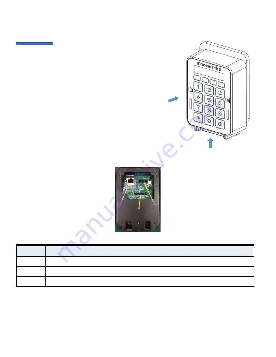
Figure 7:
Attaching Reader to Mounting Plate
To attach the reader housing to the mounting plate:
2. Affix the reader housing to the secured mounting plate.
3. Secure the reader housing to the mounting plate using proper
ESD procedures by inserting screws (supplied) into the two
seats at the bottom of the reader. The type of screws should
be 2802-8531-19 Screw 4-40 UNC x 1/2" CSK Socket
4. Apply power to the reader.
Figure 8:
Cheetah SE Reader Rear View
Table 4:
Connector Descriptions
Connectors
Description
A: Ethernet
RJ45 connector. Provides network connectivity for applications and browser based reader configuration.
B: 9-pin Molex
Ground, Power, Bus, RS485, Supervised Inputs. See "FICAM/OSDP Wiring" on page 9 and "RM Wiring" on page 10.
C: 6-pin Molex
Bus, Relays, Output, Digital/Common Ground. See "FICAM/OSDP Wiring" on page 9 and "RM Wiring" on page 10.
Molex 9-Pin Connector Properties
Table 5
on
Page 8
describes the 9-pin Molex keyed connector. Since the connector is keyed, it can only be inserted into the
reader in one configuration, that is, with pin 9 on the left and with pin 1 on the right as you face the rear of the reader.
7
Innometriks Cheetah SE Reader Quick Start Guide


