Quick Installation Guide
INNOTECH EXCA234 SERIES
EXCA234 SERIES: Outdoor Vandal Dome Camera
CAMERA INSTALLATION
1.
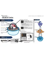
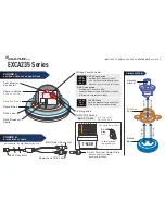
Remove the Rotation Base from the Dome Base (pull straight out).
2.
Remove the (4) Base Mounting Hole Plugs (& Base Grommet/Side
Knockout if necessary).
3.
Prepare the camera mount by drilling (4) holes using the Dome
Base Mounting Holes as a template.
4.
Determine if you are using BNC or CAT5 connections & set the
BNC/CAT5 Switch on the Camera Gimbal to the correct position.
BNC CONNECTION
5.
Determine the camera voltage requirements
(See Figure:1 Voltage
Version Label)
.
5.1
Using the RJ45 Breakout Cable, connect the BNC connector to
the RG-59 video cable, then connect the Screw Terminal Power
Plug to camera power
(See Figure:1 for switch settings & power
information).
5.2
Bring the RJ45 connector through the Base Grommet (or Side
Knockout), then attach the base to the prepared camera mount.
5.3
Insert the Camera Gimbal into the Rotation Base.
(See Figure:1
for proper alignment).
5.4
Connect the RJ45 connector on the Breakout Cable to the RJ45
jack on the Camera Gimbal, then insert the Rotation Base into the
Dome Base.
CAT5 CONNECTION
6.
Bring the user supplied CAT5 cable through the Base Grommet (or Side
Knockout), then attach the Dome Base to the prepared camera mount.
6.1
Insert the Camera Gimbal into the Rotation Base
(See Figure:1 for
proper alignment).
6.2
Connect the RJ45 connector on the user supplied CAT5 cable to the
RJ45 jack on the Camera Gimbal, then insert the Rotation Base into
the Dome Base.
6.3
Connect the RJ45 connector on the other end of the user supplied
CAT5 cable to the Innotech SmartControl® CAT5 Decoder. Maximum
distance is 1,000 ft.
POWER & ADJUSTMENTS
7.1
Apply power to the camera.
7.2
Attach the test monitor cable (provided) to the test monitor connector
on the camera gimbal & use a test monitor for lens adjustments.
7.3
Adjust the camera lens position (by rotating the Rotation Base &
Camera Gimbal), adjust the zoom & focus.
7.4
Adjust the camera OSD settings (refer to: OSD User’s Manual).
Use the test monitor cable for BNC or CAT5 Connection.
OPTIONAL: Use the OSD Remote Control for CAT5 Connection.
7.5
Remove the test monitor cable & attach the dome.
INNOTECH TECHNICAL SUPPORT 954-792-2818 OPTION #3
PACKAGE CONTENTS
•
(1) CAMERA GIMBAL/ROTATION BASE
(SNAP-LOCK)
•
(1) DOME BASE
•
(1) DOME
•
(1) RJ45 BREAKOUT CABLE
•
(1) TEST MONITOR CABLE
•
(1) SCREW TERMINAL POWER PLUG
•
(1) ALLEN WRENCH
•
(4) SCREWS
•
(4) ANCHORS


