EXCA235 Series
INNOTECH TECHNICAL SUPPORT
954.792.2818
option #3
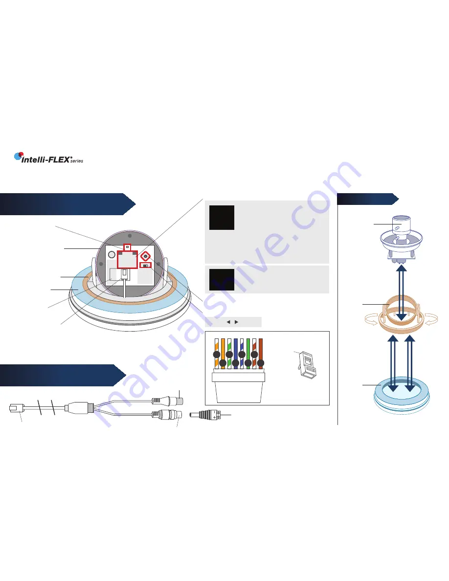
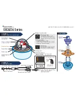
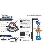
OSD Joystick
BNC/CAT5 Switch
BNC CAT5
N/A FOR 12VDC
ONLY VERSION
CAT5 Connection
•
Set BNC/CAT5 Switch to “CAT5”
•
Use CAT5 cable with SmartControl
Decoder.
(See Cat5 wiring detail below)
BNC Connection
•
Set BNC/CAT5 Switch to “BNC”
•
Use RJ45 Breakout Cable with 12VDC or 24VAC
P/S (camera auto senses voltage)
CAT5
12V AC
24V AC
BNC
INSERT
REMOVE
Camera Gimbal
ALIGN AS SHOWN
Test Monitor
Connector
Rotation Base
Dome Base
RJ45 Jack
RJ45 Breakout
Cable
RJ45 Connector
BNC Video Connector
Power Jack 12/24 Volt
Screw Terminal Power Plug
•
Observe polarity for 12VDC
•
No polarity for 24VAC
GIMBAL SYSTEM
Camera
Gimbal
Rotation
Base
Dome
Base
FIGURE 1:
CAMERA, CONTROLS & CONNECTIONS
FIGURE 2:
RJ45 BREAKOUT CABLE
12VDC Only
Use RJ45 Breakout Cable with 12VDC
P/S & Screw Terminal Power Plug
12V DC
BNC
ONLY !
CAT5 WIRING DETAIL
Clip is pointed
away from you.
T-568B
o
g
b
br
O
B
G
BR
1 2 3 4 5 6 7 8
RJ-45
Plug
Pin 1
INSERT
REMOVE
Voltage Version Label
*included with “HY”and “BNC” series only


