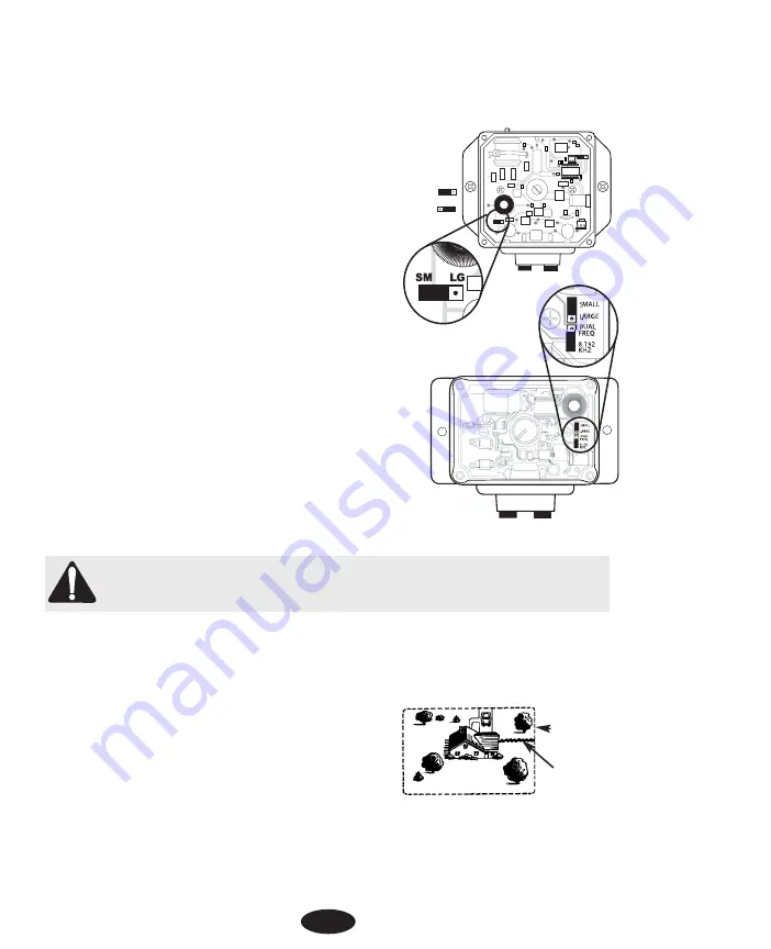
If it is necessary to change the yard size setting:
1. Turn the Field Width knob to the “off” position.
2. Remove the knob and the four screws that secure the transmitter’s cover.
3. Move the jumper to the desired yard setting. The jumper must be
in place for the transmitter to function.
•
Rechargeable Systems Only:
The jumper is located at the lower
left side of the transmitter. SM is for small yards; LG is for large
yards (see Figure 1).
•
Battery-Operated Systems Only:
The jumper is
located at right side of the transmitter. SMALL is for
small yards; LARGE is for large yards. A second
jumper is labeled "DUAL FREQ" and "8.192 KHz." This
jumper should always be in the "8.192 KHz" position
unless otherwise directed by an INNOTEK Service Center
(see Figure 2).
4. Replace the transmitter cover and the four screws.
5. Reinstall the Field Width knob with the pointer in the "off" posi-
tion.
STEP 6.
LAY OUT THE PERIMETER WIRE
IMPORTANT NOTE:
Do NOT bury the wire until you have tested the system and are sure it is working
properly. Do NOT nick or scrape the wire during installation. Improper function may result.
1. Use your drawing as a reference. Begin laying the wire around the perimeter of your containment
area to form a continuous loop. Use gradual turns at the corners with a minimum of 1meter radius.
This provides a more consistent signal field.
2. If you are using more wire than initially supplied with your
containment system, the wire connections must be water-
proof to provide a sealed connection between the wires.
Use only the supplied splices or a comparable type. Do not
use electrical tape or twisted wire nuts. This will cause an
intermittent signal or disarm the system.
3. Continue around your perimeter until you return to the start
of the loop.
4. Cut the wire.
SM LG
MED LO
SM LG
SM LG
Figure 1
Rechargeable System
Figure 2
Battery-Operated System
Wall Transmitter
Located in Garage
Perimeter Wire
Twisted Wire
to Wall
Transmitter
Installation Diagram
4

