background image

31

TECHNICAL INFORMATION

 TECHNICAL  INFORMATION

5�1    Technical  data


..2.0

Models

m.u.

15HP

Cooling performance (AT 35°C; AT 27°C)

Maximum cooling capacity Dual Power

(1)

kW

3,50

Nominal cooling power

(1)

kW

2,87

Minimum Cooling Capacity

(1)

kW

1,40

Dehumidification capacity

L/24h

1,2

total input power

kW

1,04

EER

2,74

Energy efficiency class

(2)

A

Heating performance  (AT 7°C; AT °C)

Maximum heat output Dual Power

(3)

kW

3,50

Nominal heat power

(3)

kW

2,75

Electric heater additional power

W

-

Minimum heat output

(3)

kW

1,35

Total absorbed power

(3)

kW

0,88

COP

3,12

Energy class 

A

Aeraulic data indoor

Ventilation speed

Nr.

3

Air flow at the maximum fan speed

m³/h

450

Air flow at the medium fan speed

m³/h

350

Air flow at the minimum fan speed

m³/h

300

Aeraulic data outdoor

Ventilation speed

Nr.

3

Air flow at the maximum fan speed

m³/h

550

Air flow at the medium fan speed

m³/h

460

Air flow at the minimum fan speed

m³/h

400

Electrical data

total input power

kW

1,45

Maximum absorbed current

A

6,30

Power Supply

V/F/Hz

230-1-50

Sound data

Nominal sound pressure

(4)

dB(A)

43

Minimum sound pressure level

(4)

dB(A)

29

REFRIGERATION CIRCUIT

Refrigerant

R32

Refrigerant charge

kg

0,50

Compressor

Rotary - DC Inverter

1.  Outdoor air temperature 35 °, relative humidity 50%. Ambient temperature 27 ° C; relative humidity 50%.

2.  Energy Efficiency according to Directive 626/2011

3.   Fresh air temperature 7 °C, relative humidity 72%. Room temperature 20°C, relative humidity 28%. Performance according to UNI 13141-7 

4.  Internal side sound pressure measured in  semi-anechoic chamber at a distance of 2 m.

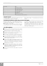
Operating Limits:

Min. Temp. cooling Ambient T 18 °C / Outdoor T -5 °C

Max Temp. cooling Ambient T 32 °C / Outdoor T 43 °C

Min. Temp. heating Ambient T 5 °C / Outdoor T -10 °C

Max Temp. heating Ambient T 25 °C/ Outdoor T 18 °C

Summary of Contents for 2.0 15 HP

Page 1: ...EN Installer manual 15 HP DC Inverter...

Page 2: ...irective 2017 1369 EU on energy labelling 2009 125 EU Directive and implementing regulation 206 2012 EU and Italian implementing regulation Legisla tive Decree no 15 of 16 02 2011 F Gas Regulation 201...

Page 3: ...ut packaging p 14 2 8 Installation site p 14 2 9 Installation minimum distances p 15 2 10 Positioning p 16 2 11 Condensation drain preparation p 19 2 12 Electric connections p 21 2 13 High low install...

Page 4: ...4 5 Technical information p 31 5 1 Technical data p 31 5 2 Dimensions p 32 5 3 RED Compliance Statement p 32 5 4 Safety p 32...

Page 5: ...proximity to sources of ignition in continuous oper ation open flames gas appliances electric stoves lighted cigarettes etc Instructions Read the instructions carefully before performing any work on...

Page 6: ...phases must be carried out exclusively by authorised and qualified personnel Any contractual or extra contractual liability for damage caused to persons animals or property due to installation adjustm...

Page 7: ...s forbidden to introduce objects and substances through the air inlet and outlet grilles It is forbidden to open the access doors of the device s internal parts without first having set main switch of...

Page 8: ...y for this purpose in accordance with their performance characteris tics 1 9 Description of the appliance The 2 0 15 HP DC Inverter range of air conditioners without an external unit are designed for...

Page 9: ...13 Room air probe 14 Internal exchanger 15 External fan 16 Condensation pump 17 External exchanger 18 Maximum level float 19 Level float 20 Condensation drain valve 21 Four way valve 22 Compressor 23...

Page 10: ...r corner installation with left hand exit Compatible with only DC Inverter versions All L00772II Accessories supplied separately Grilles and accessories Kit n 2 external grilles with fixed fins 160 mm...

Page 11: ...of combustion is minimised before starting work on systems containing flammable refrigerants The appliance must be protected against accidental im pacts to prevent mechanical damage Do not puncture o...

Page 12: ...und it when the load is lifted off the ground Avoid dangerous situations when using a hoist to lift the appliance The appliance is unbalanced on the right compressor side During transportation the app...

Page 13: ...ays be handled vertically Check if there is refrigerant inside the package using an electronic leak detector suitable for the system refrigerant If it is present the refrigeration circuit is likely da...

Page 14: ...f stackable packages In manual operation it is compulsory to respect always the maximum weight per person provided for by the national laws and standards 2 8 Installation site The location of the appl...

Page 15: ...appro priate base it could cause damage to persons or property if it should detach from its base The unit should not be installed in a position where the air flow is aimed directly at the people nearb...

Page 16: ...ls 8 HP On Off 10 HP DC Inverter 12 HP DC Inverter 12 HP DC Inverter ELEC D 16 mm condensate drain E anti lifting bracket hole F 202 mm holes for air channelling for models 15 HP DC Inverter B C F IN...

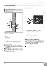
Page 17: ...d with caution in the vicinity of the outer wall in order to avoid the breakage of plaster around the hole Take precautions so that the drilled material does not fall on persons and objects below Posi...

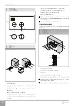
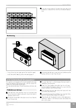
Page 18: ...rings are in tension hook the chains to the counterflange cut off the excess of chain When painting the dampers use water based paints suit able for plastic surfaces to avoid problems with the move me...

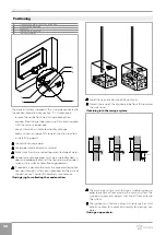
Page 19: ...tube are shown be low Preliminary warnings If the line flows into a container e g a tank do not close the container hermetically and avoid immersing the drain ing pipe into the water The hole for the...

Page 20: ...e of water Condensate drainage pipes must be insulated for both in door and outdoor sections of the house to avoid conden sation on the surface and or freezing problems If needed it is possible to emp...

Page 21: ...device enabling the com plete disconnection of the appliance in overvoltage III cat egory conditions Please check that the power supply is provided with suit able protections against overloads and or...

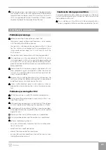
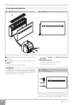
Page 22: ...ic panels and grilles p 25 To access the connections unscrew the screws of the electrical panel remove the electrical panel cover Connection The appliance leaves the factory fully wired and equip ped...

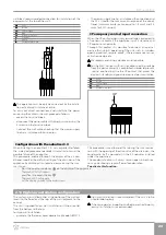
Page 23: ...CP contact that places the device in standby and guarantees correct post ventilation GR Grey BR Brown YG Yellow Green BL Blue CP Presence contact G R G R C P G R BL YG BR Configuration with the nebuli...

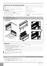
Page 24: ...thetic lower cover kit Code GB0737II 2 Fixing screws supplied with the optional kit GB0737II 3 Right support bracket for the flap A B 1 3 2 180 Configuration After adjusting the air outlet flap positi...

Page 25: ...and in the event of a power failure 2 17 hotel function Keep the key pressed for 10 seconds If the En function is enabled the dehumidification and Auto functions are disabled only ventilation heating...

Page 26: ...26 Installation 2 1 2 20 Assembly of aesthetic panels and grilles To assemble positioning the aesthetic panel insert the two screws Screw in the two screws insert the filter insert the grid 2 1...

Page 27: ...c Smoking in the vicinity of the appliance is prohibited Using a mobile phone near the appliance is prohibited Using leak detectors with halogen lamps is prohibited 3 2 Routine maintenance The routine...

Page 28: ...hetic panels and grilles p 26 extract the filter by lifting it remove the dust from the filter with a vacuum cleaner or by washing it in running water allow it dry put the filters back on top of the c...

Page 29: ...or other high energy consumption appliances such as small ovens steam irons hot plates etc Displayed faults In the event of a malfunction the display shows an alarm code The appliance still retains so...

Page 30: ...hould drain freely through the specific pipe In the event of an alarm check that the condensation pipe is not bent or obstructed thus prevent ing the water from flowing out Use of the appliance Object...

Page 31: ...r 3 Air flow at the maximum fan speed m h 550 Air flow at the medium fan speed m h 460 Air flow at the minimum fan speed m h 400 Electrical data total input power kW 1 45 Maximum absorbed current A 6...

Page 32: ...mm 165 Empty weight kg 41 0 Wall hole diameter mm 202 Wall holes distance mm 293 5 3 RED Compliance Statement Compliance with 2014 53 EU Radio Equipment Direc tive RED In accordance with Article 10 8...

Page 33: ...33 NOTE...

Page 34: ...34 NOTE...

Page 35: ...35 NOTE...

Page 36: ...realized by Innova technical dept INNOVA S r l Via I Maggio 8 38089 Storo TN ITALY tel 39 0465 670104 fax 39 0465 674965 info innovaenergie com N420630A Rev 01...

Reviews: