background image


Safety Precautions 


SAFETY FIRST! 


3100j 3 


SAFETY FIRST! 


This manual describes common test procedures used 
by experienced service technicians. Many test procedures 
require precautions to avoid accidents that can result in 
personal injury, and/or damage to your vehicle or test 
equipment. Always read your vehicle's service manual and 
follow its safety precautions before and during any test or 
service procedure. 

ALWAYS

 observe the following general 

safety precautions: 

When an engine is running, it produces carbon monoxide, 
a toxic and poisonous gas. To prevent serious injury or 
death from carbon monoxide poisoning, operate the 
vehicle 

ONLY

 in a 

well-ventilated

 area. 

To protect your eyes from propelled objects as well as hot 
or caustic liquids, 

always

 wear 

approved

 safety eye 

protection. 

When an engine is running, many parts (such as the 
coolant fan, pulleys, fan belt etc.) turn at high speed. To 
avoid serious injury, always be aware of moving parts. 
Keep a safe distance from these parts as well as other 
potentially moving objects. 

Engine parts become very hot when the engine is running. 
To prevent severe burns, avoid contact with hot engine 
parts. 

Before starting an engine for testing or troubleshooting, 
make sure the parking brake is engaged. Put the 
transmission in 

park

 (for automatic transmission) or 

neutral

 (for manual transmission). Block the drive wheels 

with suitable blocks. 

Connecting or disconnecting test equipment when the 
ignition is 

ON

 can damage test equipment and the 

vehicle's electronic components. Turn the ignition 

OFF


before connecting the diagnostic tool to or disconnecting 
the diagnostic tool from the vehicle’s Data Link Connector 
(DLC). 

To avoid personal injury, instrument damage and/or 

damage to your vehicle; do not use the diagnostic tool 

before reading this manual.


N L

D

R

P

Summary of Contents for 3100j

Page 1: ......

Page 2: ...s 52 VIEWING SRS DTCs 54 ERASING DIAGNOSTIC TROUBLE CODES DTCs 56 ABOUT REPAIRSOLUTIONS 58 I M READINESS TESTING 62 ADDITIONAL FUNCTIONS SYSTEM TEST MENU 68 VIEWING VEHICLE INFORMATION 73 RESETTING THE OIL MAINTENANCE LIGHT 75 USING THE DLC LOCATOR 76 BATTERY ALTERNATOR MONITOR 77 VIEWING TRIP CYCLE PROCEDURES 81 VIEWING THE FIRMWARE VERSION 82 THE TOOL LIBRARY 83 ADJUSTMENTS AND SETTINGS 85 USING...

Page 3: ...tic and import This sophisticated program in the vehicle s main computer system is designed to detect failures in a range of systems and can be accessed through a universal OBD2 port which is usually found under the dashboard For all OBD systems if a problem is found the computer turns on the CHECK ENGINE light to warn the driver and sets a Diagnostic Trouble Code DTC to identify where the problem...

Page 4: ...er Easy To View The diagnostic tool retrieves stored codes Freeze Frame data and System Status Codes I M Monitor Status and Freeze Frame data are displayed on the diagnostic tool s LCD display screen System Status is indicated by LED indicators Easy To Define Read code definitions from the diagnostic tool s LCD display View Freeze Frame data View Anti Lock Brake System ABS DTCs View Supplemental R...

Page 5: ...ine is running many parts such as the coolant fan pulleys fan belt etc turn at high speed To avoid serious injury always be aware of moving parts Keep a safe distance from these parts as well as other potentially moving objects Engine parts become very hot when the engine is running To prevent severe burns avoid contact with hot engine parts Before starting an engine for testing or troubleshooting...

Page 6: ...pors are highly flammable To prevent an explosion keep all sparks heated items and open flames away from the battery and fuel fuel vapors DO NOT SMOKE NEAR THE VEHICLE DURING TESTING Don t wear loose clothing or jewelry when working on an engine Loose clothing can become caught in the fan pulleys belts etc Jewelry is highly conductive and can cause a severe burn if it makes contact between a power...

Page 7: ...tes must be OBD2 compliant this includes all Domestic Asian and European vehicles Some 1994 and 1995 vehicles are OBD2 compliant To find out if a 1994 or 1995 vehicle is OBD2 compliant check the following 1 The Vehicle Emissions Control Information VECI Label This label is located under the hood or by the radiator of most vehicles If the vehicle is OBD2 compliant the label will state OBD II Certif...

Page 8: ...ver and screw on the back of the diagnostic tool Adjustments After Battery Installation The first time the unit is turned on you must select the desired display language English French or Spanish and unit of measurement USA or Metric as follows 1 Press the POWER LINK button to turn the diagnostic tool ON The Select Language screen displays 2 Use the UP and DOWN buttons as necessary to highlight th...

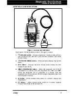
Page 9: ... Menu 3 DTC button Displays the DTC screen and or scrolls the LCD display to view DTCs 4 POWER LINK button When the diagnostic tool IS NOT connected to a vehicle turns the diagnostic tool On and Off When the diagnostic tool is connected to a vehicle links the diagnostic tool to the vehicle s PCM to retrieve diagnostic data from the computer s memory 5 M button When pressed while linked to a vehicl...

Page 10: ...Indicates there is a possible problem A Pending DTC is present and or some of the vehicle s emission monitors have not run their diagnostic testing 12 RED LED Indicates there is a problem in one or more of the vehicle s systems The red LED is also used to show that DTC s are present DTCs are shown on the diagnostic tool s LCD display In this case the Malfunction Indicator Check Engine lamp on the ...

Page 11: ...s available that makes it possible to upload retrieved data to a personal computer 6 Diagnostic Tool Internal Battery icon When visible indicates the diagnostic tool batteries are low and should be replaced If the batteries are not replaced when the battery symbol is on all 3 LEDs will light up as a last resort indicator to warn you that the batteries need replacement No data will be displayed on ...

Page 12: ...e type Indicates the type of code being displayed Generic Stored Generic Pending Generic permanent etc 14 Severity Indicates the level of severity for the priority code code number 1 as follows 1 Service should be scheduled and repairs made when convenient This DTC typically has no immediate threat to essential system components in the short term 2 Repair immediately if drivability issues are pres...

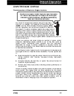
Page 13: ...el delivery and spark timing This made it difficult for vehicle manufacturers to meet the new standards A new Engine Control System had to be designed and integrated with the engine controls to meet the stricter standards The new system had to Respond instantly to supply the proper mixture of air and fuel for any driving condition idle cruising low speed driving high speed driving etc Calculate in...

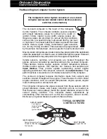
Page 14: ...erature sensors throttle position sensors fuel injectors etc Sensors and switches are input devices They provide signals representing current engine operating conditions to the computer Actuators are output devices They perform actions in response to commands received from the computer The on board computer receives information inputs from sensors and switches located throughout the engine These d...

Page 15: ...he dashboard to alert the driver The indicator lights only when an emissions related problem is detected The computer also assigns a numeric code for each specific problem that it detects and stores these codes in its memory for later retrieval These codes can be retrieved from the computer s memory with the use of a diagnostic tool or a scan tool On Board Diagnostics Second Generation OBD2 In add...

Page 16: ...The primary objective of the OBD2 system is to comply with the latest regulations and emissions standards established by CARB and the EPA The Main Objectives of the OBD2 System are To detect degraded and or failed emissions related components or systems that could cause tailpipe emissions to exceed by 1 5 times the Federal Test Procedure FTP standard To expand emissions related system monitoring T...

Page 17: ...ach Monitor Some Monitors only require the ignition key to be turned On for them to run and complete their diagnostic testing Others may require a set of complex procedures such as starting the vehicle when cold bringing it to operating temperature and driving the vehicle under specific conditions before the Monitor can run and complete its diagnostic testing Monitor Has Has Not Run The terms Moni...

Page 18: ...gine temperature rises at least 40 F 22 C from its temperature before starting and reaches at least 160 F 70 C The PCM uses warm up cycles as a counter to automatically erase a specific code and related data from its memory When no faults related to the original problem are detected within a specified number of warm up cycles the code is erased automatically DIAGNOSTIC TROUBLE CODES DTCs Diagnosti...

Page 19: ...section of the system that is malfunctioning P 0 2 0 1 B C P U Body Chassis Powertrain Network Generic Manufacturer Specific Generic P Codes and Manufacturer Specific B C and U Codes Includes both Generic and Manufacturer Specific Codes 0 1 2 3 Identifies what section of the system is malfunctioning Identifies the system where the problem is located P Code systems are listed below B C and U Code s...

Page 20: ...he MIL On when the failure is first found If the failure causes a severe misfire that may cause damage to the catalytic converter the MIL flashes once per second The MIL continues to flash as long as the condition exists If the condition that caused the MIL to flash is no longer present the MIL will light steady On A DTC is saved in the computer s memory for later retrieval A Freeze Frame of the c...

Page 21: ...nsure the correct operation of the various emissions related components and systems a diagnostic program was developed and installed in the vehicle s on board computer The program has several procedures and diagnostic strategies Each procedure or diagnostic strategy is made to monitor the operation of and run diagnostic tests on a specific emissions related component or system These tests ensure t...

Page 22: ...inputs and outputs from sensors actuators switches and other devices that provide a signal to the computer The Monitor checks for shorts opens out of range value functionality and rationality Rationality Each input signal is compared against all other inputs and against information in the computer s memory to see if it makes sense under the current operating conditions Example The signal from the ...

Page 23: ...rily saves the fault in its memory as a Pending Code The MIL is not commanded on at this time If the fault is found again on the second trip under similar conditions of engine speed load and temperature the computer commands the MIL On and the code is saved in its long term memory Type 2 misfires are the most severe type of misfire When a Type 2 misfire is sensed on the first trip the computer com...

Page 24: ...Oxides of Nitrogen combustion temperatures must be kept below 2500 F The EGR system recirculates small amounts of exhaust gas back into the intake manifold where it is mixed with the incoming air fuel mixture This reduces combustion temperatures by up to 500 F The computer determines when for how long and how much exhaust gas is recirculated back to the intake manifold The EGR Monitor performs EGR...

Page 25: ...the oxygen sensor signal for air fuel mixture corrections In order for the computer to enter closed loop operation the oxygen sensor must reach a temperature of at least 600 F The oxygen sensor heater helps the oxygen sensor reach and maintain its minimum operating temperature 600 F more quickly to bring the vehicle into closed loop operation as soon as possible The Oxygen Sensor Heater Monitor is...

Page 26: ... heat to operating temperature to work properly The Secondary Air System Monitor checks for component integrity and system operation and tests for faults in the system The computer runs this Monitor once per trip The Secondary Air System Monitor is a Two Trip monitor If a fault is found on the first trip the computer temporarily saves this fault in its memory as a Pending Code The computer does no...

Page 27: ...vel greater than atmospheric pressure This increase in pressure helps to ensure compete combustion of the air fuel mixture The Boost Pressure System Monitor checks for component integrity and system operation and tests for faults in the system The computer runs this Monitor once per trip The Boost Pressure System Monitor is supported by compression ignition vehicles only The Boost Pressure System ...

Page 28: ...on vehicles only The PM Filter Monitor is a Two Trip Monitor If a fault is found on the first trip the computer temporarily saves the fault in its memory as a Pending Code The computer does not command the MIL on at this time If the fault is sensed again on the second trip the computer commands the MIL On and saves the code in its long term memory OBD2 Reference Table The table below lists current...

Page 29: ... Oxygen Sensor Monitor Once per trip 1 2 1 3 trips 40 Oxygen Sensor Heater Monitor Once per trip 1 2 1 3 trips 40 Exhaust Gas Recirculation EGR Monitor Once per trip 1 2 1 3 trips 40 Evaporative Emissions Controls Monitor Once per trip 1 2 1 3 trips 40 Secondary Air System AIR Monitor Once per trip 1 2 1 3 trips 40 NMHC Monitor Once per trip 1 2 1 3 trips 40 NOx Adsorber Monitor Once per trip 1 2 ...

Page 30: ...u retrieve You can also provide this information to your mechanic to assist in diagnosis and help avoid costly and unnecessary repairs It is important for you to complete this form to help you and or your mechanic have a clear understanding of your vehicle s problems NAME DATE VIN YEAR MAKE MODEL ENGINE SIZE VEHICLE MILEAGE VIN Vehicle Identification Number found at the base of the windshield on a...

Page 31: ...STALLS No symptoms Right after starting When shifting into gear During steady speed driving Right after vehicle comes to a stop While idling During acceleration When parking IDLING CONDITIONS No symptoms Is too slow at all times Is too fast Is sometimes too fast or too slow Is rough or uneven Fluctuates up and down RUNNING CONDITIONS No symptoms Runs rough Lacks power Bucks and jerks Poor fuel eco...

Page 32: ...erating With headlights on During acceleration Mostly driving downhill Mostly driving uphill Mostly driving level Mostly driving curvy roads Mostly driving rough roads DRIVING HABITS Mostly city driving Highway Park vehicle inside Park vehicle outside Drive less than 10 miles per day Drive 10 to 50 miles per day Drive more than 50 miles per day GASOLINE USED 87 Octane 89 Octane 91 Octane More than...

Page 33: ...connected Check the air filter ducts for holes rips or cracks Make sure all engine belts are in good condition Check for cracked torn brittle loose or missing belts Make sure mechanical linkages to engine sensors throttle gearshift position transmission etc are secure and properly connected See your vehicle s service manual for locations Check all rubber hoses radiator and steel hoses vacuum fuel ...

Page 34: ...publish valuable repair manuals Haynes Publications 861 Lawrence Drive Newbury Park California 91320 Phone 800 442 9637 Web www haynes com Mitchell 1 14145 Danielson Street Poway California 92064 Phone 888 724 6742 Web www m1products com Motor Publications 5600 Crooks Road Suite 200 Troy Michigan 48098 Phone 800 426 6867 Web www motor com FACTORY SOURCES Ford GM Chrysler Honda Isuzu Hyundai and Su...

Page 35: ...the diagnostic tool to the DLC 3 Connect the diagnostic tool cable connector to the vehicle s DLC The cable connector is keyed and will only fit one way If you have problems connecting the cable connector to the DLC rotate the connector 180 and try again If you still have problems check the DLC on the vehicle and on the diagnostic tool Refer to your vehicle s service manual to properly check the v...

Page 36: ...gnostic Tool fails to link to the vehicle s computer a Communi cation Error message shows on the Diagnostic Tool s display Ensure your vehicle is OBD2 compliant See VEHICLES COVERED on page 5 for vehicle compliance verification information Verify the connection at the DLC and verify the ignition is ON Turn the ignition OFF wait 5 seconds then back ON to reset the computer Press the POWER LINK butt...

Page 37: ...esired vehicle then press the ENTER button Proceed to step 10 To select a new vehicle use the UP and DOWN buttons as necessary to highlight New Vehicle then press the ENTER button Proceed to step 9 9 When New Vehicle is chosen from the Select Vehicle screen the Select Year screen displays Use the UP and DOWN buttons as necessary to highlight the desired vehicle model year then press the ENTER butt...

Page 38: ...if you wish to reselect the vehicle use UP and DOWN buttons as necessary to highlight No then press the ENTER button to return to the Select Year screen 10 After approximately 10 60 seconds the diagnostic tool will retrieve and display any Diagnostic Trouble Codes Monitor Status and Freeze Frame Data retrieved from the vehicle s computer memory The diagnostic tool will display a code only if codes...

Page 39: ...he upper lower right hand corner of the code display area to indicate the presence of additional information Use the UP and DOWN buttons as necessary to view the additional information 12 Read and interpret Diagnostic Trouble Codes system condition using the LCD display and the green yellow and red LEDs The green yellow and red LEDs are used with the LCD display as visual aids to make it easier to...

Page 40: ...re considered Generic Universal All Generic DTC definitions are the same on all OBD2 equipped vehicles The diagnostic tool automatically displays the code definitions for Generic DTC s DTC s that start with P1 and some P3 are Manufacturer Specific codes and their code definitions vary with each vehicle manufacturer 13 If more than one code was retrieved press the DTC button as necessary to display...

Page 41: ...o take the vehicle to a professional to have it serviced complete the PRELIMINARY VEHICLE DIAGNOSTIC WORKSHEET on page 28 and take it together with the retrieved codes freeze frame data and LED information to aid in the troubleshooting procedure To prolong battery life the diagnostic tool automatically shuts Off approximately three minutes after it is disconnected from the vehicle The DTCs retriev...

Page 42: ...s Press the SYSTEM MENU button to return to the System Menu 2 When finished press and release the DTC button to return to the OBD2 DTC screen THE SYSTEM MENU The System Menu provides the ability to retrieve enhanced DTCs Anti Lock Brake System ABS and Supplemental Restraint System SRS DTCs for most Audi BMW Chrysler Jeep Ford Mazda GM Isuzu Hyundai Kia Mercedes Benz Toyota Lexus and Volkswagen veh...

Page 43: ...Lock Brake System ABS DTCs access an Oil Maintenance Light reset function and return to the Global OBD2 mode To view Enhanced DTCs 1 With the diagnostic tool on the Code Retrieval screen press and release the SYSTEM MENU button The System Menu displays 2 Use the UP and DOWN buttons as necessary to highlight OEM Enhanced then press the ENTER button 3 If enhanced communication is not supported by th...

Page 44: ...er Press the POWER LINK button to continue If the diagnostic tool cannot link to the vehicle s computer after three attempts the message Contact Technical Support displays Press the SYSTEM MENU button to return to the System Menu Turn the ignition off and discon nect the diagnostic tool Contact Technical Support for assistance 2 To read the display Refer to DISPLAY FUNCTIONS on page 8 for a descri...

Page 45: ...was retrieved press the DTC button as necessary to display additional codes one at a time Whenever the Scroll function is used to view additional codes the diagnostic tool s communication link with the vehicle s computer disconnects To re establish communication press the POWER LINK button again 4 When the last retrieved DTC has been displayed and the DTC button is pressed the diagnostic tool retu...

Page 46: ...essage displays while the test is in progress If the diagnostic tool fails to link to the vehicle s computer a Communication Error message shows on the diagnostic tool s display Ensure your vehicle is OBD2 com pliant See VEHICLES COVERED on page 5 for vehicle compliance verification information Verify the connection at the DLC and verify the ignition is ON Turn the ignition OFF wait 5 seconds then...

Page 47: ...al Cycle the overdrive switch if equipped A One moment please message displays while the test is in progress 5 To read the display Refer to DISPLAY FUNCTIONS on page 8 for a description of LCD display elements A visible icon indicates that the diagnostic tool is being powered through the vehicle s DLC connector A visible icon indicates that the diagnostic tool is linked to communicating with the v...

Page 48: ... one at a time Whenever the Scroll function is used to view additional codes the diagnostic tool s communication link with the vehicle s computer disconnects To re establish communication press the POWER LINK button again 7 When the last retrieved DTC has been displayed and the DTC button is pressed the diagnostic tool returns to the Priority code To view additional enhanced DTCs repeat steps 1 th...

Page 49: ...le icon indicates that the diagnostic tool is being powered through the vehicle s DLC connector A visible icon indicates that the diagnostic tool is linked to communicating with the vehicle s computer The upper left corner of the display shows the Diagnostic Trouble Code DTC the number of the code currently being displayed and the total number of codes retrieved and the type of code The related co...

Page 50: ...Priority code To view additional enhanced DTCs repeat steps 1 through 4 above To exit the enhanced mode press the SYSTEM MENU button to return to the System Menu Use the UP and DOWN buttons as necessary to highlight Global OBD then press the ENTER button to return to the Global OBD2 mode Honda Acura Enhanced DTCs When Honda OEM Enhanced is chosen from the System Menu the diagnostic tool retrieves ...

Page 51: ...ic Trouble Code DTC the number of the code currently being displayed and the total number of codes retrieved and the type of code The related code definition is shown in the lower section of the LCD display If the definition for the cur rently displayed code is not available an advisory mes sage shows on the diagnos tic tool s LCD display I M MONITOR STATUS icons are not displayed when viewing enh...

Page 52: ...l OBD2 mode Toyota Lexus Enhanced DTCs When Toyota OEM Enhanced is chosen from the System Menu the diagnostic tool retrieves OEM enhanced DTCs from the vehicle s computer 1 A One moment please message displays while the diagnostic tool retrieves the selected DTCs If the diagnostic tool fails to link to the vehicle s computer a Communication Error message shows on the diagnostic tool s display Ensu...

Page 53: ... displayed when viewing enhanced DTCs In the case of long code definitions a small arrow is shown in the upper lower right hand corner of the code display area to indicate the presence of additional information Use the UP and DOWN buttons as necessary to view the additional information The diagnostic tool will display a code only if codes are present in the vehi cle s computer memory If no codes a...

Page 54: ...stic tool retrieves the selected DTCs If the vehicle does not support ABS communication an advisory message shows on the diagnostic tool s display Press the SYSTEM MENU button to return to the System Menu If the diagnostic tool fails to link to the vehicle s computer a Linking Failed message shows on the diagnostic tool s display Verify the connection at the DLC and verify the ignition is ON Turn ...

Page 55: ...s are not displayed when viewing ABS DTCs In the case of long code definitions a small arrow is shown in the upper lower right hand corner of the code display area to indicate the presence of additional information Use the DOWN button to view the additional information The diagnostic tool will display a code only if codes are present in the vehicle s computer memory If no codes are present a No AB...

Page 56: ...hows on the diagnostic tool s display Press the SYSTEM MENU button to return to the System Menu If the diagnostic tool fails to link to the vehicle s computer a Communication Error message shows on the diagnostic tool s display Ensure your vehicle is OBD2 com pliant See VEHICLES COVERED on page 5 for vehicle compliance verification information Verify the connection at the DLC and verify the igniti...

Page 57: ...are not displayed when viewing SRS DTCs In the case of long code definitions a small arrow is shown in the upper lower right hand corner of the code display area to indicate the presence of additional information Use the UP and DOWN buttons as necessary to view the additional information The diagnostic tool will display a code only if codes are present in the vehicle s computer memory If no codes ...

Page 58: ...to a not run flashing condition To set all of the Monitors to a DONE status an OBD2 Drive Cycle must be performed Refer to your vehicle s service manual for information on how to perform an OBD2 Drive Cycle for the vehicle under test The diagnostic tool must be connected to the vehicle s DLC to erase the codes from the computer s memory If you press the ERASE button when the diagnostic tool is not...

Page 59: ... ON DO NOT start the engine Press the ENTER button to continue If the erase was successful a confirmation message shows on the display Press the SYSTEM MENU button to return to the System Menu If the erase was not successful and ECU error code 22 is present an advisory message displays Start the engine and maintain vehicle speed at 0 then press the ERASE button to try again If the erase was not su...

Page 60: ...he issues associated with your vehicle Verified Fixes The Verified Fixes page lists the most likely repair s needed by your vehicle based on the DTCs retrieved It includes cost estimates for the repair s based on your geographic location provides access to detailed instructions for performing the repair s and includes links to supplemental information including articles and videos related to the a...

Page 61: ...ket cost and minimize personal inconvenience Through detailed analysis of historical repair information supplied by technician across the country RepairSolutions is able to provide highly accurate predictions of potential service and repair requirements based on your vehicle s year make model and mileage The Predicted Repairs page provides a list of predicted repairs for your vehicle over the next...

Page 62: ... are discovered only under real world driving conditions When an issue that affects personal safety is found or if a vehicle does not meet Federal safety standards the Government mandates that the vehicle manufacturer issue a safety recall Safety recalls are official notices that describe known vehicle issues as well as the related safety concerns Repairs performed to address a safety recall are p...

Page 63: ...l Mini USB Cable included with tool Minimum System Operating Requirements Windows OS Requirements Windows XP Windows Vista 32 64 bit editions Windows 7 32 64 bit editions Windows 8 Windows 8 1 Windows 10 Minimum Hardware Requirements 50 MB free disk space 128 MB RAM Pentium processor or better One available USB port USB 2 0 preferred Other Requirements Internet Connection Internet Explorer 5 5 Net...

Page 64: ...ed by the Federal Government is called I M 240 On I M 240 the vehicle under test is driven under different speeds and load conditions on a dynamometer for 240 seconds while the vehicle s emissions are measured Emissions tests vary depending on the geographic or regional area in which the vehicle is registered If the vehicle is registered in a highly urbanized area the I M 240 is probably the type ...

Page 65: ...ted their diagnosis and testing and which ones have not yet run and completed testing and diagnosis of their designated sections of the vehicle s emissions system If a Monitor was able to meet all the conditions required to enable it to perform the self diagnosis and testing of its assigned engine system it means the monitor HAS RUN If a Monitor has not yet met all the conditions required for it t...

Page 66: ...k may be performed 3 Other areas may only require that some but not all Monitors indicate a Has Run status before an Emissions Test Smog Check may be performed Monitors with a Has Run status indicate that all the required conditions they needed to perform diagnosis and testing of their assigned engine area system have been met and all diagnostic testing has completed successfully Monitors with a H...

Page 67: ...tus of each Monitor a solid Monitor icon shows Monitor Has Run status a flashing Monitor icon indicates Has Not Run status Take this information to an emissions professional to determine based on your test results if your vehicle is ready for an Emissions Test Smog Check 3 RED LED Indicates there is a problem with one or more of the vehicle s systems A vehicle displaying a red LED is definitely no...

Page 68: ... to check for Monitor Run Status Use the following procedure to determine I M Readiness Monitor Status 1 Using retrieved Diagnostic Trouble Codes DTCs and code definitions as a guide and following manufacturer s repair procedures repair the fault or faults as instructed 2 After the fault or faults have been repaired connect the diagnostic tool to the vehicle s DLC and erase the code or codes from ...

Page 69: ...Trip Drive Cycle is performed properly the Monitor icon on the diagnostic tool s LCD display changes from flashing to solid indicating that the Monitor has run and finished its diagnostic testing If after the Monitor has run the MIL on the vehicle s dash is not lit and no stored or pending codes associated with that particular Monitor are present in the vehicle s computer the repair was successful...

Page 70: ...r Performs a check of the vehicle s battery and alternator system to ensure the system is operating within acceptable limits Trip Cycle Procedure Lets you view trip cycle procedures for a selected vehicle monitor Firmware Version Displays the diagnostic tool s firmware version Tool Library Displays the Tool Library menu which provides access to OBD1 and OBD2 DTC libraries and to definitions for Mo...

Page 71: ...xhaust system Catalytic Converters The name of an O2 sensor identifies its location in the exhaust system The name of each O2 sensor is made up of three parts O2S XX YY or O2S X Y O2S this is the basic designation for all O2 sensors X or XX These characters identify the location of the O2 sensor in relation to a cylinder bank An O2 sensor for cylinder bank 1 is identified by the designation 1 or B...

Page 72: ... button to return to the Main Menu 3 Use the UP and DOWN buttons as necessary to highlight the O2 sensor for which you wish to view test results then press the ENTER button 4 When test results have been retrieved data for the selected sensor test will show on the diagnostic tool s display 5 When you have finished viewing the retrieved test data To view test results for the next available sensor us...

Page 73: ...ent to the vehicle s on board computer The Select Test screen displays The screen shows all tests applicable to the vehicle under test Refer to the vehicle s service repair manual for information related to non continuous tests If OBD monitor test data is not presently stored in the vehicle s computer an advisory message shows on the diagnostic tool s display Press the M button to return to the Ma...

Page 74: ...le manufacturer determines the criteria and method for stopping the test once it has been started BEFORE using the EVAP Test function refer to the vehicle s service repair manual to determine the procedures necessary to stop the test 1 From the System Test menu use the UP and DOWN buttons as necessary to highlight EVAP Test then press the ENTER button 2 A One moment please message displays while t...

Page 75: ...hicle s Calibration Verification Number s CVNs required by ODB2 regulations CVNs are used to determine if emission related calibrations for the vehicle under test have been changed One or more CVNs may be returned by the vehicle s computer 1 While linked to a vehicle press and release the M button The Main Menu displays 2 Use the UP and DOWN buttons as necessary to highlight Vehicle Information th...

Page 76: ... DOWN buttons as necessary to view the entire list 5 When you have finished viewing the list of available modules press the M but ton to exit Viewing In use Performance Tracking IPT The diagnostic tool can retrieve In use Performance Tracking IPT statistics for monitors supported by the vehicle under test Two values are returned for each monitor the number of times that all conditions necessary fo...

Page 77: ...message shows on the diagnostic tool s display Press the M button to return to the Main Menu 5 When you have finished viewing the statistics press the M button to exit RESETTING THE OIL MAINTENANCE LIGHT Refer to VEHICLE APPLICATIONS MAKES COVERED on page 99 for vehicle makes covered 1 While linked to the vehicle press the M button The Main Menu displays 2 Use the UP and DOWN buttons as necessary ...

Page 78: ... to highlight Yes then press the ENTER button to continue A status message displays while the oil reset is in progress 4 When the reset process has competed a confirmation message shows on the Scan Tool s display Press the M button to return to the Main Menu If the oil reset was not successful an advisory message displays To perform the oil reset by procedure use the use the UP and DOWN buttons bu...

Page 79: ...ry to highlight the desired model then press the ENTER button The DLC Location screen for the selected vehicle displays The DLC Location screen shows the selected vehicle make and model a description of the DLC location and whether the DLC is covered or uncovered and includes a picture of the DLC location 6 When you have finished viewing the DLC location press any hotkey to exit the DLC Locator BA...

Page 80: ...ace the transmission in PARK or NEUTRAL and set the parking brake Make a visual check of the battery s condition If the battery terminals are corroded or other damage is present clean or replace the battery as appropriate For unsealed batteries make sure the water level in each cell is above the battery plates Turn the ignition on DO NOT start the engine 5 Press the ENTER button to begin the batte...

Page 81: ...ntinue An instructional message shows on the diagnostic tool s display 8 Start the vehicle s engine Allow the engine to run for several seconds then turn the engine off Repeat for a total of three start stop cycles If the diagnostic tool did not detect cranking status for the vehicle s engine an advisory message shows on the diagnostic tool s display Press the ENTER button to repeat the battery ch...

Page 82: ...accelerator pedal to raise engine speed to 2000 RPM and maintain the engine speed When engine speed is within the required range the alternator test begins A progress screen shows the Engine RPM and countdown timer When the countdown timer expires an instructional message shows on the diagnostic tool s display 6 Turn the vehicle s headlights off and return the engine to idle speed A One moment ple...

Page 83: ...ons as necessary to highlight Trip Cycle Procedures then press the ENTER button A One moment please message displays while the diagnostic tool retrieves Monitor status from the vehicle s computer 3 When Monitor status has been retrieved the Trip Cycle Procedures menu displays Depending on Monitor status you can view Trip Cycle procedures for Monitors Incomplete or Monitors Complete If Trip Cycle P...

Page 84: ...t available an advisory message shows on the diagnostic tool s display Use the UP and DOWN buttons as necessary to highlight Back then press the ENTER button to return to the Main Menu 6 The Trip Cycle Procedure screen shows the specific set of operating procedures that ensure the vehicle is driven in such a way that all the required Enabling Criteria for the Monitor to run and complete its diagno...

Page 85: ...scrip tions of the meaning of the diagnostic tool SYSTEM STATUS LEDs 1 While linked to the vehicle press the M button The Main Menu displays 2 Use the UP and DOWN buttons as necessary to highlight Tool Library then press the ENTER button The Tool Library menu displays Viewing Tool Icon Descriptions The I M MONITOR STATUS icons on the diagnostic tool s LCD display provide an indication of the Compl...

Page 86: ...ect Library screen displays 2 Use the UP and DOWN buttons as necessary to highlight OBD2 Library then press the ENTER button The Select Manufacturer screen displays 3 Use the UP and DOWN buttons as necessary to highlight the desired vehicle manufacturer then press the DTC button The Enter DTC screen displays The screen shows the code P0001 with the P highlighted 4 Use the UP and DOWN buttons as ne...

Page 87: ...tic tool provide a visual indication of the I M Readiness status of the vehicle under test The LED Definitions function provides a description of the meanings of the green yellow and red SYSTEM STATUS LEDs 1 From the Tool Library menu use the UP and DOWN buttons as necessary to highlight LED Definitions then press the ENTER button The LED Meaning screen displays The screen provides a description o...

Page 88: ...The Main Menu displays 2 Use the UP and DOWN buttons as necessary to highlight Tool Settings then press the ENTER button The Tool Setting menu displays 3 Make adjustments and settings as described in the following paragraphs Adjusting Display Brightness 1 Use the UP and DOWN buttons as necessary to highlight Adjust Brightness in the Tool Settings Menu then press the ENTER button The Adjust Brightn...

Page 89: ...s menu without making changes press the M button Enabling Disabling Navigational Footers Navigational footers are shown at the bottom of most display screens They show which hotkey to press to return to the topmost menu for the current function 1 Use the UP and DOWN buttons as necessary to highlight Footer Messages in the Tool Settings menu then press the ENTER button The Footer Messages screen di...

Page 90: ...ighlight Language Selection in the Tool Settings menu then press the ENTER button The Language Selection screen dis plays The currently selected display language is highlighted 2 Use the UP and DOWN buttons as necessary to highlight the desired display language 3 When the desired display language is highlighted press the ENTER button to save your changes and return to the Tool Settings menu shown ...

Page 91: ...necessary to highlight the desired unit of measurement 3 When the desired unit of measurement value is selected press the ENTER button to save your changes and return to the Tool Settings menu To exit the Unit of Measurement screen and return to the Tool Settings menu without making changes press the M button Exiting the Tool Settings Menu Press the M button to return to the Main Menu ...

Page 92: ...R LINK button to turn the diagnostic tool on If the diagnostic tool s batteries are low a warning message displays Replace the batteries before con tinuing 2 If more than one vehicle is stored in the diagnostic tool s memory the Vehicle Selection menu displays Use the UP and DOWN buttons as necessary to highlight the desired vehicle then press the ENTER button If there are no vehicles currently st...

Page 93: ...r the priority DTC When all DTCs have been displayed and the DTC button is pressed the diagnostic tool displays the first enhanced DTC stored in memory Press the DTC button to scroll through all stored enhanced DTCs 4 When you have finished viewing data in the diagnostic tool s memory press and release the POWER LINK button to turn the diagnostic tool off ...

Page 94: ...F XXXX X Catalyst Temperature Bank 1 Sensor 2 CAT Temp 21 C F XXXX X Catalyst Temperature Bank 2 Sensor 1 CAT Temp 22 C F XXXX X Catalyst Temperature Bank 2 Sensor 2 Command EGR XXX X Commanded EGR Command EVAP XXX X Commanded Evaporative Purge Command TAC XXX X Commanded Throttle Actuator Dist DTC Clr km mile XXXXX Distance since DTC Cleared Dist MIL ON km mile s XXXXX Distance Traveled while MIL...

Page 95: ...Status Fuel Sys 1 OL Fault Fuel System 1 Status Fuel Sys 1 CL Fault Fuel System 1 Status Fuel Sys 2 OL Fuel System 2 Status Fuel Sys 2 CL Fuel System 2 Status Fuel Sys 2 OL Drive Fuel System 2 Status Fuel Sys 2 OL Fault Fuel System 2 Status Fuel Sys 2 CL Fault Fuel System 2 Status IAT C F XXX XXX Intake Air Temperature LOAD Value XXX X Absolute Load Value LTFT B1 XXX X Long Term Fuel Trim Bank 1 L...

Page 96: ...mA X XXX Bank 2 Sensor 3 O2S Current O2S B2 S3 V V X XXX Bank 2 Sensor 3 O2S Voltage O2S B2 S4 V X XXX Bank 2 Sensor 4 O2S B2 S4 mA mA X XXX Bank 2 Sensor 4 O2S Current O2S B2 S4 V V X XXX Bank 2 Sensor 4 O2S Voltage O2S Location O2S11 Oxygen Sensor Bank 1 Sensor 1 O2S Location O2S12 Oxygen Sensor Bank 1 Sensor 2 O2S Location O2S13 Oxygen Sensor Bank 1 Sensor 3 O2S Location O2S14 Oxygen Sensor Ban...

Page 97: ... Off Power Take Off Status Rel TPS XXX X Relative Throttle Position Spark Adv deg XX Ignition Timing Advance 1 Cylinder STFT B1 XXX X Short Term Fuel Trim Bank 1 STFT B1 S1 XXX X Bank 1 Sensor 1 STFT B1 S2 XXX X Bank 1 Sensor 2 STFT B1 S3 XXX X Bank 1 Sensor 3 STFT B1 S4 XXX X Bank 1 Sensor 4 STFT B2 XXX X Short Term Fuel Trim Bank 2 STFT B2 S1 XXX X Bank 2 Sensor 1 STFT B2 S2 XXX X Bank 2 Sensor ...

Page 98: ...Generic Global OBD2 PID List 96 3100j Tool Display Unit Value PID Description Veh Speed km h mph XXX XXX Vehicle Speed Sensor Warm up DTC Clr XXX Warm ups since DTC Cleared ...

Page 99: ...Vehicle Makes supported by the diagnostic tool are shown below Please visit www innova com for a complete list of vehicles covered ACURA JEEP AM GENERAL KIA BUICK LEXUS CADILLAC LINCOLN CHEVROLET MERCURY CHRYSLER NISSAN DODGE OLDSMOBILE FORD PLYMOUTH GENERAL MOTORS PONTIAC GEO RAM GMC SATURN HONDA SCION HUMMER SRT HYUNDAI TOYOTA INFINITI ...

Page 100: ...Vehicle Makes supported by the diagnostic tool are shown below Please visit www innova com for a complete list of vehicles covered ACURA JEEP AM GENERAL KIA BUICK LEXUS CADILLAC LINCOLN CHEVROLET MERCURY CHRYSLER NISSAN DODGE OLDSMOBILE FORD PLYMOUTH GENERAL MOTORS PONTIAC GEO RAM GMC SATURN HONDA SCION HUMMER SRT HYUNDAI TOYOTA INFINITI ...

Page 101: ...e diagnostic tool are shown below Please visit www innova com for a complete list of vehicles covered ACURA LEXUS AUDI LINCOLN BMW MERCEDES BENZ BUICK MERCURY CADILLAC MINI CHEVROLET MITSUBISHI CHRYSLER NISSAN DODGE OLDSMOBILE EAGLE PONTIAC FIAT RAM FORD SAAB FREIGHTLINER SATURN GMC SCION HONDA SMART HUMMER SPRINTER INFINITI SUZUKI ISUZU TOYOTA JAGUAR VOLKSWAGEN JEEP VOLVO LAND ROVER ...

Page 102: ...perated such as starting the vehicle when cold driving at steady speed cruising accelerating etc DTC s Diagnostic Trouble Code s EGR Exhaust Gas Recirculation System Status An indication of whether or not a vehicle s emissions related system are operating properly and are ready for Inspection and Maintenance testing EPA Environmental Protection Agency EVAP Evaporative Emissions System Fault Code S...

Page 103: ...l Module Pending Code A code recorded on the first trip for a two trip code If the fault that caused the code to be set is not detected on the second trip the code is automatically erased STFT Short Term Fuel Trim is a program in the vehicle s computer designed to add or subtract fuel from the vehicle to compensate for operating conditions that vary from the ideal A F ratio The vehicle uses this p...

Page 104: ...Notes 102 3100j ...

Page 105: ...Notes 3100j 103 ...

Page 106: ...Notes 104 3100j ...

Page 107: ...of God or if the product was altered or repaired by anyone other than the Manufacturer s Service Center The Manufacturer under no circumstances shall be liable for any consequential damages for breach of any written warranty of this unit This warranty gives you specific legal rights and you may also have rights which vary from state to state This manual is copyrighted with all rights reserved No p...

Page 108: ......
Reviews: