background image


Innova S.r.l.


Pag. 30


N420227A_ManualeHRC_ Rev06.EN.docx


8. ACCESSORIES


The unit can 'be accompanied by some installation accessories. 

Read the instructions below for the installation of each accessory. 


8.1 DFM fixing Dima wall  


The wall mounting template allows you to remove 

the unit ' 

from the wall without the need for removal of the 

fixing screws to the wall. 

The template is installed to the wall using screws 

and dowels; 

on the template is then fixed the motor mounting 

which will be 'breath from the threaded leaflets 

supplied. 


For inspection of the heat exchanger and the 

internal parts of the tube, it will not 'remove the 

screws to the wall, but only to remove the flyers of 

Reverse locking of the template. 


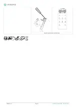
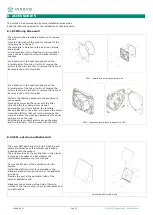
DFM - Installation of fixing template wall 

For inspection of the heat exchanger and the 

internal parts of the tube, it will not 'remove the 

screws to the wall, but only to remove the flyers of 

Reverse locking of the template. 


Perform the following steps with the appliance is 

not powered. 

Proceed by removing the cover with the filter. 

Unlocking the four clamps from its seat. 

Unscrew the four flyers locking the template. 

Paying attention to the wires, will remove the motor 

mounting platform that will remain 'raised by the 

wires and allow' the cleaning operations of the heat 

exchanger and the tube. 

Refit the motor support plate, arrange the wires 

and the terminals; refit the cover with the filter. 


DFM - Inspection and tube exchanger with DFM 


8.2 GEM - exterior aesthetics Grid 


The outer GEM aesthetic grid, and 'a finishing grid 

external alternative to the external grid already 

'supplied with the product. 

The grid provides for the construction in two pieces. 

A piece and 'consists of a flat plate for the 

comfortable attachment of the wall grid. 


Secure the flat part of the aesthetic grid with 

dowels. 

Install the plastic circular rack provided in the 

standard product through the hole of the aesthetic 

grid plate. 

Overlap the part of the aesthetic finish of the 

exterior aesthetics grid. 


Make sure the centering of the hole of the grid, 

relative to the tube in order to avoid load losses and 

air obstructions. 


exterior aesthetics GEM Grid 

Summary of Contents for HRC 02 E

Page 1: ...itale sociale int vers 150 000 CF P IVA 01827470228 Iscrizione REA nr 180610 Num reg Imprese TN 10656 Numero Meccanografico TN025148 www innovaenergie com Pag 1 N420227A_ManualeHRC_ Rev06 EN docx INST...

Page 2: ...AND DISPOSAL 7 2 INSTALLATION Pag 2 1 GENERALITY 8 2 2 POSITIONING AND ASSEMBLY UNIT 8 3 ELECTRICAL CONNECTIONS Pag 3 1 GENERALITY 11 3 2 CONNECTION AND POWER SUPPLY VERSION S 11 3 3 WIRING UNIT VERSI...

Page 3: ...T 27 6 4 FUNZIOAMENTO WIRELESS COMMUNICATION AND INFORMATION 27 6 5 WARNING AND BATTERY REPLACEMENT OF REMOTE CONTROL 27 7 ALARMS Pag 7 1 GENERALITY 29 7 2 PROBLEMS RELATED TO THE OPERATION OF THE UNI...

Page 4: ...ts requires observance of some basic safety rules The use of the equipment to disabled people and non assisted is prohibited It s forbidden to touch the appliance with bare feet and with wet or damp b...

Page 5: ...any incomplete link of the covers may cause overheating of the terminals Installations carried out outside of the warnings of this manual or use outside of the operating limits will void Instantly th...

Page 6: ...air filtering fundamental for people with allergies the electronic speed control motor guarantee a low consumption of electricity inspection and maintenance of easy access through panel with snap clos...

Page 7: ...of the closing panels and doors of inspections If there are no channels installed on one of the 4 aeraulic sockets provide adequate protection to install a network Check the power supply and the grou...

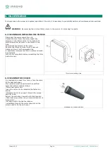
Page 8: ...in the environment due to which there may be a reflux gas discharge into the environment 2 2 POSITIONING AND ASSEMBLY UNIT To mount the drive you must Realize for the whole thickness of the wall a mi...

Page 9: ...action exchanger Sprinkle the hole made with cement mortar or polyurethane foam Insert the telescopic tube into the drilled hole and bringing the part of the tube with a larger diameter to the outer w...

Page 10: ...eat exchanger from the inside to the final part of the tube with smaller diameter Figure 4 Positioning Outdoor Grill Fig 5 Inserting exchanger Detach the cover from the motor support by pressing on th...

Page 11: ...maximum achievable load The data related are indicated on the unit nameplate E forbidden to enter the electrical wiring in the unit except where specified in this booklet Use cables and electrical co...

Page 12: ...on so as to create an air inlet and a contemporary extraction If connected in parallel the motors work with a sense of rotation in parallel so as to double the instantaneous flow rate of the various c...

Page 13: ...ype CR3032 supplied Wireless Remote Control 3 6 WIRING UNIT AND VERSION Connect the power supply 230 1 50 to each installed unit The communication between devices takes place through wirless communica...

Page 14: ...functioning of the system Carefully follow the setup procedure described below 4 2 CONFIGURATION UNIT MASTER 1 Power on all units in the system The units will be powered and in standby mode 2 Move cl...

Page 15: ...holxd the info button for at least 5 seconds The central signaling LED will flash rapidly as shown in the illustration signaling the entry in the configuration Login Slave configuration procedure 2 B...

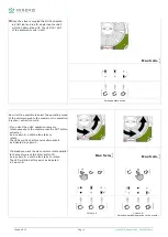
Page 16: ...in operation injection extraction cycle If you want the units operation recovery rotate opposite to the master press the OUT button extraction as in column A until the fan starts to rotate The LEDs w...

Page 17: ...ich then resumes operation Max 5 cm Slave configuration Confirmation 5 Approach with the remote control to the second slave and repeat the configuration for all the remaining slaves B Max 5 cm Procedu...

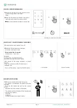
Page 18: ...pling mode enabled 3Long press the AUTO button to decouple all slaves from the system Procedures disaccoppiametno slave 4 5 PROCEDURE FOR REST DECOUPLING MASTER OF THE REMOTE CONTROL 1Press the ON OFF...

Page 19: ...n speed selector gives the possibility to choose the maximum speed minimum speed and the system shutdown The speed variation allows to modify the flow rate of air exchanged with the outside in any ope...

Page 20: ...high turn the knob until the position with the DT piu marked line Contrary on a spring day where the temperature difference is minimal or close to zero rotate the knob to position with the DT piu thin...

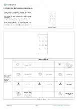
Page 21: ...d fan unit Above a few buttons it is present signaling led through which the request for information to the ventilating unit will indicate the operating status Remote Version E Here you are shown the...

Page 22: ...nd cycle 3 now select the fan speed between min med max EXAMPLE In this picture and selected mode automatic cycle and the speed media With regard to the single extraction or single function input the...

Page 23: ...raction time to optimize the system s regenerative recovery cycle At the first activation of the Auto mode after 10 minutes and subsequently every 12 hours the Master ventilation unit performs the pro...

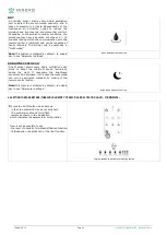
Page 24: ...unction BRIGHTNESS SENSOR A light sensor allows every single ventilation units alone to adopt the minimum speed extra low during the night If necessary the brightness sensors can be excluded in this c...

Page 25: ...d between Low Medium and High Selecting humidity threshold 3 Choose whether to enable or disable the function of the light sensor Led Night On Function active Led Night Off function off Press the AUTO...

Page 26: ...um cleaner or blow it with compressed air E possible to immerse the filter in water and wash it periodically Allow to dry completely before reinstalling the filter inside the unit filter for extractin...

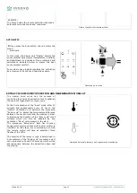
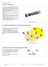
Page 27: ...ain within the heat exchanger reinstallare through the motor support and the screws used to fix the unit cover Views units for general cleaning 6 4 OPERATION AND INFORMATION ON WIRELESS COMMUNICATION...

Page 28: ...Innova S r l Pag 28 N420227A_ManualeHRC_ Rev06 EN docx Replacing remote control batteries...

Page 29: ...blades Clean the filters Increase the speed of rotation Clean piping heat exchanger Make the fan impellers Insufficient exchanger Yield Scambiatore clogged Time cycle set improperly Clean the surface...

Page 30: ...appliance is not powered Proceed by removing the cover with the filter Unlocking the four clamps from its seat Unscrew the four flyers locking the template Paying attention to the wires will remove th...

Page 31: ...Kit The kit provides for the possibility to install the product with the discharge does not direct on the wall but with the direction of the angular flow For example if you have the shoulders between...

Page 32: ...o isolate the outside of the product avoiding thermal transmittances towards the outer surfaces of the product The isolation and consists of a double shell coated insulating material With the insulati...

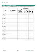
Page 33: ...of the plant in order to keep track of the settings made in order to facilitate any maintenance interventions UNIT LOCAL ENVIRONMENT PARAMETER SETTINGS Direction of rotation Cycle in Ans HR MIN HR MED...

Page 34: ...Innova S r l Pag 34 N420227A_ManualeHRC_ Rev06 EN docx 11 2016 Rev 06 Technical Assistance Center The data contained in this catalog may be changed by the manufacturer without notice...

Reviews: