i
4
HIGHER
SP
LIMIT
o
400 C
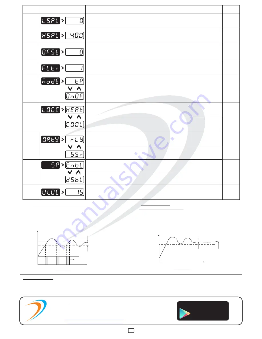
Sets the maximum limit for set point adjustment. It can be set from LSPL value to
maximum specified range of selected sensor.
PROCESS
VALUE
OFFSET
INPUT
FILTER
CONTROL
MODE
CONTROL
LOGIC
o
0 C
o
1 C
T.P
HEAT
Function of this parameter is to add/subtract a constant value to the measured PV to
obtain Final PV for control applications. This parameter value needs to be altered for one
of the following reason :
(i) To compensate for known thermal gradient.
(ii)To match the display values with another recorder or indicator measuring the same PV.
Controller is equipped with an adaptive digital filter which is used to filter out any
extraneous pulses on the PV. Filtered PV Value is used for all PV dependent functions. If
PV signal is fluctuating due to noise, increase the filter time constant value.
User can select between ON-OFF or T.P action algorithm to be adopted for output.
(Refer User Guide)
This parameter will appear only if selected control mode is ON-OFF.
User can select heating logic in which OP1 will remain ON till PV < SP.
(PV increases when output is ON.)
This parameter will appear only if selected control mode is ON-OFF.
User can select cooling logic in which OP1 will remain ON till PV > SP.
(PV decreases when output is ON.)
OUTPUT
TYPE
RELAY
User has to set this parameter very carefully in accordance with the output used.
(Separate terminals for RELAY & SSR : - Refer Electrical Installation)
Select Relay if LOAD is connected via Contactor. Whenever user selects Relay, Cycle time
will automatically set to 16 sec. User can modify cycle time via Control List.
Select SSR if LOAD is connected via SSR (DC voltage pulses). Whenever user selects
SSR , Cycle time will automatically set to 1sec. User can modify cycle time via Control List.
15
Default USER LOCK CODE is 15 to access Control & Configuration List.
User has a choice to set its own USER LOCK CODE between 1 to 9999, this is to prevent
unauthorized access of Control & Configuration List.
USER
LOCK
CODE
PARA
METER
DESCRIPTION
DEFAULT
DISPLAY
LOWER
SP
LIMIT
o
0 C
Sets the minimum limit for set point adjustment. It can be set from minimum specified
range of selected sensor to HSPL value.
SET
POINT 1
If Enabled, User can View & edit the Set point in USER list.
If disabled, User can only View the Set Point but Can not edit it in USER list.
ENABLE
2)
TIME PROPORTIONAL ACTION:
In this mode, ON & OFF time of output (Relay/SSR)varies
proportionally in every cycle (cycle time settable by user)
depending on the deviation of PV w.r.t. SP. This action
Starts/continues only when PV enters or is within the band.
(As shown in Fig : 3.3)
3)
MANUAL RESET
(OFFSET ADJUSTMENT):
In some application, after adopting-Time proportionating action,
system may stabilize at particular temperature over a period of
time which can be different than the set value. This steady state
(error) offset can be eliminated by setting this value equal and
opposite to the existing offset. (As shown in Fig : 3.4)
TIME PROPORTIONAL ACTION
ACTIVE ZONE
Fig: 3.3
AMB
0
TEMP ( C)
SP
OUT PUT
ON
100 %
ON
100 %
OFF
100 %
PROPORTIONAL BAND (P.BND)
SET BY USER
time
AMB
0
TEMP ( C)
SP
Fig: 3.4
OFFSET
after offset adjustment
TIME
SP
: Set Point Value(set temp.)
SSR
: Solid State Relay
T.P.
: Time Proportional
T/C
: Thermocouple
NC
: Normally Close terminal of relay
NO
: Normally Open terminal of relay
OP1
: Output 1
PV
: Process Value (actual temp.)
C.A.
: Control Action
CJC
: Cold junction compensation
CM
: Common terminal of relay
LWC
: Lead wire (Length)
compensation
ABBREVIATION :
Innovative Instruments
On
Google Play
206, New Sonal Link Service Industrial Premises Co-op Society Ltd,
Building No.2, Link Road, Malad (W), Mumbai - 400064.
Tel: 022-66939916/17/18;
E-mail :
Website :
sales@innovativeinstruments.co.in
www.innovativeinstruments.co.in
Mfgd by: Innovative Instruments & Controls LLP
i
OIM AI-5X41 - V2.0 Page 4 of 4


