background image

5   


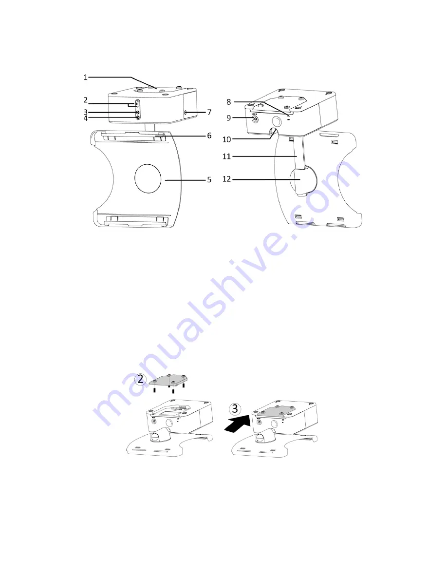
LOCATION   OF   CONTROLS   


1.   Mounting   Plate   

2.   Power   Button   &   Indicator   

3.   Volume   Down   Button   

4.   Volume   Up   Button   

5.   Tablet   Dock   

6.   Adapter   Grooves   

7.   Release   Button   

8.   AC   Power   Cord   

9.   3.5mm   AUX   IN   socket   

10.   Latch   

11.   Arm   

12.   Shaft   

SETUPS/CONNECTIONS   

ASSEMBLY   

Remove   all   packing   materials   and   dispose   of   them   properly.   

1.   Place   the   card   paper   template   in   the   location   where   you   want   to   mount   the   

unit.   Drill   the   screw   holes   accordingly.       


2.   Slide   the   Mounting   Plate   out   and   install   the   Mounting   Plate,   with   included   

screws,   in   the   chosen   location   (fig.   2).   

3.   Once   the   Mounting   Plate   is   positioned,   slide   the   unit   onto   the   Mounting   

Plate   (fig.   3).   

Note:

   The   unit   can   also   act   as   a   freestanding   dock,   sitting   

upright   on   a   flat   surface   such   as   a   table   or   countertop.


Summary of Contents for ITIU+730

Page 1: ...o Speakers TABLE OF CONTENTS IMPORTANT SAFETY INSTRUCTIONS 2 BEFORE USE 4 COPYRIGHT 4 LOCATION OF CONTROLS 5 SETUPS CONNECTIONS 5 ASSEMBLY 5 CONNECTING THE 3 5MM AUX IN CABLE 6 CONNECTING TO A POWER S...

Page 2: ...as a bathroom kitchen sink or pool Keep the apparatus away from heaters stoves etc Never leave the apparatus in an area exposed to direct sunlight where there could be a considerable rise in temperatu...

Page 3: ...hould be moved with care to avoid damage or injury 20 Never try to disassemble batteries Do not put batteries in direct sunlight nor throw them into fire or heater This can result in injury 21 Refer a...

Page 4: ...set contact your dealer 3 When removing the power plug from the wall outlet always pull directly on the plug never pull the cord 4 Do not attempt to clean the unit with chemical solvents as this might...

Page 5: ...materials and dispose of them properly 1 Place the card paper template in the location where you want to mount the unit Drill the screw holes accordingly 2 Slide the Mounting Plate out and install the...

Page 6: ...ease button to release the latch fig 1 2 Meanwhile pull the Tablet Dock down gently as the latch releases Once it is in position a slight click will be heard fig 2 3 The Adapters for iPad 2 and iPad 3...

Page 7: ...the Tablet Dock by moving the Arm back Once in position a slight click will be heard fig 8 9 Disconnect the power cord from the working electrical outlet especially when the unit will not be in use f...

Page 8: ...t all power supply devices After one minute re plug the power cord SPECIFICATIONS AMPLIFIER section Output Power 2 x 2W Frequency Response 60 to 20 000 Hz SPEAKER SYSTEM section Type 1 way Impedance 4...

Page 9: ...harmful interference to radio or television reception which can be determined by turning the equipment off and on the user is encouraged to try to correct the interference by one or more of the follow...

Page 10: ...ackaging or reasonable substitute to prevent damage Customer Must include full name shipping address and telephone number inside of package No return will be shipped back to a PO Box or APO address Pl...

Page 11: ...11 7301204011E...

Reviews: