NV200 Family User Manual
<< Back to Contents
Copyright © Innovative Technology Ltd 2016
Doc: NV200 Family Manual
Version: 1.0
Page 20 of 119
4.2
Bezel Mounting
4.2.1
Bezel Fitting
WARNING!
Ensure bezel is secured to
validator
The bezel should be secured to the validator head
using screws if the NV200 is being installed and
transported inside a host machine.
Information
Check bezel fixing screw
length before installation.
The length of the bezel fixing M4 screws must be
no more than 12 mm in length.
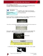
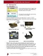
The bezel is designed to be removed and refitted easily. To remove or refit the
bezel, access to the note path is required
–
the top cover must be open fully to allow
access to the bezel mounting area.
Validator note path cover
Bezel assembly
Bezel connector socket
Bezel removal and fitting
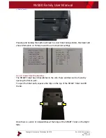
Fitting the bezel: Lift the upper cover by pulling the latch forward as shown in
picture 1. Connect the cable from the bezel assembly (as shown in picture 2) to the
socket located on the front of the validator head (as shown in picture 3) and slide
the assembly down into place and close the note path upper cover (as shown in
picture 4). If required, the bezel can be secured in place with two M3 screws - these
are fitted in the two holes at the bottom of the bezel.
When fitting the bezel please ensure the NV200 is removed from the cashbox to prevent any issues
with fitting.
Screw mounting holes
Cover
release
latch
Electrical
connector
1
2
3
4
Summary of Contents for NV200 Spectral
Page 1: ...Doc GA02031 Version 1 0 ...


