TNi21
07 April 2016
Page
25/38
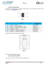
7.3. Control logic bundle
Comprises a UL-approved cable, style 2464 80°C 300V, 500mm long as standard, fitted with a Molex
connector reference
8 contacts:
Pin
Function
Colour of wires
(AWG24)
1
Input no.1
– On / Off
Vert /
Green
2
Input no. 2
– Direction of rotation
Jaune /
Yellow
3
Input no. 3
– Torque set-point 0-10V or PWM
Bleu /
Blue
4
Input no. 4
– Speed set-point 0-10V or PWM
Orange /
Orange
5
Logical earth - 0V DC
Noir /
Black
6
Output no. 1
– Encoder 12 or 24 pts per rev
Marron /
Brown
7
Output no. 2
– Torque limit reached
Violet /
Purple
8
Output no. 3
– Actual direction of rotation
Rouge /
Red
a label attached to the motor provides this information:
References for the connector to be used:
On the board: Molex series 43045
On the cable: Molex series 43020
If the cable is more than 3m long, tests should be conducted in situ.
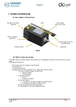
Figure 5
Figure 6
8
6
4
2
7
5
3
1


