Installation & Connections
Overview
200R204-000
Innovx FastSwitch Ethernet Switch
2-7
Issue 2
Installation and Operation Manual
Interface Port Descriptions
Ethernet (LAN) Ports
(Interface “A”, “B” and “C” in
Figure 2-1
and
Figure 2-2
)
All FastSwitch ethernet ports provide 10/100BASE-T Ethernet connectivity and require an RJ45-
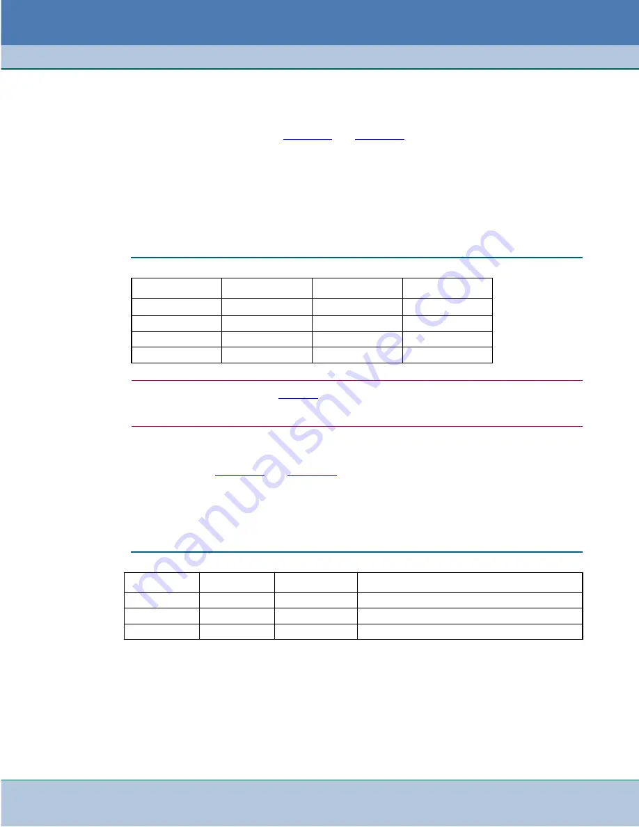
to-RJ45 straight-thru or crossover cable (GDC S-078H010-XXX or S-078H011-XXX). The table
below describes Ethernet port pinouts. Note that any port can be used as a logical uplink port to
cascading FastSwitch cards, FastRoute static router cards or other hub/bridge devices.
•
For FastSwitch 9-Port, the upper connector at the rear panel is Port 9.
•
For FastSwitch 18-Port unit, the upper connector at the rear panel is Port 9 and the
lower connector is Port 18.
Note
The Ethernet port pinouts shown in
Table 2-3
apply when Auto MDI/MDIX is turned off and the MDIX option
is set to No Force. When FastSwitch is set to Auto MDI/MDIX, the actual Tx and Rx pinouts depend on the
result of Auto MDI/MDIX negotiation.
Craft Port
(Interface “D” in
Figure 2-1
and
Figure 2-2
)
The FastSwitch craft (or console) port is an RS-232-compatible DB25 connector at the rear shelf
slot. This interface supports 9600bps asynchronous data and provides terminal interface control of
the unit by direct connection to a local VT100-compatible ASCII terminal. Connection to the Craft
port requires a DB25-to-RJ45 adapter (GDC P/N 029H210-001). The table below describes the
Craft port pinouts
Table 2-3
Ethernet LAN Port Pinouts (RJ45s)
RJ45 Pin
Signal
Direction
Description
1
Rx+
To FastSwitch
Receive Data
2
Rx-
To FastSwitch
Receive Data
3
Tx+
From FastSwitch
Transmit Data
6
Tx-
From FastSwitch
Transmit Data
Table 2-4
Craft Port Pinouts (DB25)
DB25 Pin
Signal
Direction
Description
7
Signal Ground
-
Signal Ground
3
RD
From FastSwitch
Receive Data - Supervisory data to the terminal
2
SD
To FastSwitch
Transmit Data - Supervisory data from the terminal
Summary of Contents for FastSwitch
Page 61: ......


