background image


19 

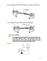
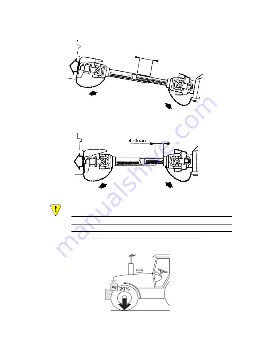
Fig. 8: Appropriate length of PTO shaft at the machine on the ground 


Fig.9: Appropriate length of the guard at machine lifted. 


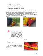
5.4 Tractor stability 


At attachment of the machine on the tractor always take 
care  about  allowed  weight  of  the  attachment  and  axle 
load.  First  axle  of  the  tractor  should  always  be  loaded 
with min.20% of the weight of the tractor itself. 


Fig. 10 


1/3 cevi 

Summary of Contents for EURO MINI

Page 1: ... R E EU UR RO O M MI IN NI I O OP PE ER RA AT TI IN NG G I IN NS ST TR RU UC CT TI IO ON NS S S SP PA AR RE E P PA AR RT TS S L LI IS ST T I IT T I IS S M MA AN ND DA AT TO OR RY Y T TO O R RE EA AD D A AN ND D F FO OL LL LO OW W T TH HE ES SE E I IN NS ST TR RU UC CT TI IO ON NS S B BE EF FO OR RE E C CA AR RR RY YI IN NG G O OU UT T A AN NY Y O OP PE ER RA AT TI IO ON N ...

Page 2: ...rating of the machine 15 5 Transport and attachment of the machine 16 Transport to the customer 16 Attachment and detachment from the tractor 16 Fitting the PTO shaft 18 Stability of the tractor 19 6 Adjustment and setting up 20 Regulating the height of cut 20 Offsetting 20 Belt tension adjustment 21 7 Operating 22 8 After the job done 24 Cleaning 24 9 Maintenance 25 Oil level control 26 Greasing ...

Page 3: ...e material appropriate technical characteristics and after sales services go together with your choice For eventual questions our stuff is always at your disposal We will specially respect your suggestions and observations that can be of a great help for future development of the machine Through all the past of our company experiances from the praxis represent a basement of development and innovat...

Page 4: ...the operator s other people s and animal s safety apart from the correct functioning of the machine In case of doubt do not experiment call INO after sales service instead or a specialized INO dealer It is mandatory to read these instructions to understand the operating of the machine In the case of re sale of the machine it is necessary to give these instructions to the new owner A meaning of dec...

Page 5: ...Directive Machine 89 392 CEE and following additions 91 368 CEE 93 44 CEE and 93 68 CEE Regulations UNI EN 292 1 and 292 2 Machinery Safety Regulation SIST EN 745 Rotary and flail mowers safety A producer can ensure normal operating of the machine only with use of original spare parts INO is not responsible for any damage or injuries if the user doesn t consider the rules in this book INO is not r...

Page 6: ...e of non genuine spare parts Non respecting these rules Overloading of the machine see Table nr 1 limited values 1 3 Identification of the machine Each machine is fitted with an identification plate with the following data producer and address CE sign name of the machine type weight identification number and year of production Fig 1 MULČER EURO MINI 150 300 kg 2012 123 ...

Page 7: ...linkage combi 5 Rear roller 6 Upper linkage point 7 skid 8 sliding tubes 2 1 Noise The sound level of this machine as measured at the operator s ear ranges from 70 to 90 dB when the rear window of tractor is open We recommend the use of ear protectors 3 8 7 2 1 6 5 4 ...

Page 8: ...etting cm 270 300 344 linkage cat 300 400 400 width mm I I I length mm 147 163 203 height mm 86 86 86 Rotor shaft rpm min 1 81 81 81 2 3 Optional equipment According to the working conditions we recommend the following optional quipment Y blade for cutting material till max 3 cm in diameter Standard Hammers for cutting material till max 4 cm in diameter Maximal thickness of the material depends on...

Page 9: ...ctions among operating is too late 4 Security and warning decals on the machine are very important Respect them always 5 Even when using the machine correctly stones or other objects may be thrown on a long distance Therefore nobody must stand within the danger area Special attention must be paid when working near roads or buildings 6 Use tractor with the cabin 7 Whenever using public roads respec...

Page 10: ... machine PTO shaft hydraulic pipes 18 Before leaving the tractor with the machine attached disconnect the tractor put the machine steadily on the ground with the hydraulic lift apply the hand brake and if the ground is steeply slooping wedge the tractor Take out the starting key 19 Do not enter the zone between the tractor and the machine It is strongly forbidden to be in this zone if the tractor ...

Page 11: ... shaft must be in good order 3 Take care that all guards on the PTO shaft are in proper position during transport or operating Respect the producer s instructions 4 The PTO shaft must be assembled or diassambled only with the engine stopped and the starting key removed 5 The guards of the PTO shaft must be fixed to the machine and to the tractor with chains to prevent rotation 6 Before starting al...

Page 12: ... operating Hydraulic system 1 Take care Hydraulics is under very high pressure 2 At connecting the pipes on the tractor check that the pressure is not too low 3 We recommend that an official service tests the pipes before operating and than at least ones per year Damaged or worn pipes should be replaced immediately with others of the same specification 4 at checking pipes it is necessary to wear p...

Page 13: ... 3 Periodically check that bolts and nuts are tighten properly 4 At maintaining it is sometimes necessary to lift the machine It is mandatory to put under the machine an appropriate support to avoid falling the machine at eventual damage on hydraulics 5 Use the gloves and appropriate tools at changing sharp parts of the machine to avoid injuries 6 Used oils and greases should be removed according ...

Page 14: ...n operations 2 Keep at a safety distance from the machine to avoid the risk of projection of objects 3 Never remove the guards while the parts of the machine are moving It is dangerous to injure the hands 4 Keep at a safety distance from the machine to avoid the risk of cutting the feet 5 It is forbidden to mount on the machine because of the risk of fall ...

Page 15: ... shield 2 Belt shield 3 Warning decals 4 Flap guard 5 Rubber guard 4 Description and operating of the machine Standard machine is combi front Fig 6 or rear mounted with Y blades optional Fig 4 or hammer blades as standard Fig 5 3 1 5 4 2 ...

Page 16: ... Fig 4 Fig 5 Fig 6 Operator manuals are made for all types of the machine All special details are described for each type separately 5 Transport and attachment of the machine 5 1 Transport to the customer ...

Page 17: ...r bring the tractor lower lines near the machine to the points corresponding to the pins Insert the pins and secure them with the spring clips Fit the top link raise the machine to a perpendicular position with the ground Adjust the two tractor lower linkage stabilizers thus fixing the machine to the tractor in a central position Connect the hydraulic cylinders and check if it works 3 point hitch ...

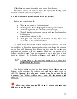
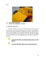
Page 18: ...ine laying on the ground minimum overlapping of the tubes mustn t be less than 1 3 of total length Cut too long part of the tube and clean the edges Cut on the proper length also the guard as on Fig 9 Measure the length when the PTO shaft is in horisontal position Grease before putting them together Too long PTO shaft can seriously damage tractor or flail mower Never put PTO shaft on the tractor w...

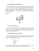
Page 19: ... length of the guard at machine lifted 5 4 Tractor stability At attachment of the machine on the tractor always take care about allowed weight of the attachment and axle load First axle of the tractor should always be loaded with min 20 of the weight of the tractor itself Fig 10 1 3 cevi ...

Page 20: ...the tractor or and with adjusted rear roller of the machine Fig 12 The min height of cut should be between 1 3 cm The machine always run on the rear roller and not on the skids Fig 11 Fig 12 Working tools never touch the ground The skids are only the protection against injuries They do not touch the ground 6 2 Offsetting the machine has in standard equipment a hydraulic offsetting Fig 13 Fig 13 1 ...

Page 21: ...ting key taken out Appropriate tension is reached when at pressure with the power of 100N 10 kg a deviation of the belt of 1 5 cm is reached Adjust correct belt tension with automatic belt tension position under the angle 20 22 Fig 14 The angle is defined with the arrow Fig 14 1 After 2 hours of operating it is necessary to tighten the bolts on taper lock Fig 16 Tighten the bolts in succession in ...

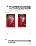
Page 22: ...0 or 1000 If necessary change the number of rpm from 540 Fig16 on 1000 rpm Fig 17 or in the opposite way Fig 16 540 rpm Fig 17 1000 rpm Adjustment of rpm is done with repositioning of the pulleys Standard is 540 rpm Change the position of the pulleys if you need to change rpm on the flail mower from 540 on 1000 Caontact INO servicing dep for more info ...

Page 23: ... Stop immediately with operating Switch off PTO shaft check rotor shaft and components and change damaged or broken missingg parts If vibrations are still on the rotor shaft it must be balanced before operating Before starting flail mower always check that rpm on PTO shaft recommend to those on the connecting axle on the flail mower Flail mower is set on 540 rpm as standard On request it can be se...

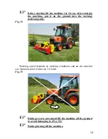
Page 24: ...t on the ground into the working position gently Fig 18 Working speed depends on working conditions and on the material cut Optimal speed is between 3 8 km h Fig 19 During reverse movement lift the machine off the ground to avoid damaging it Fig 19 During turning lift the machine ...

Page 25: ...central position Check the condition of the rotor shaft working blades and if they are tightened well bolts nuts PTO shaft must be disconnected during transport At disconnecting the machine respect the warning rules for connecting the machine Put the machine on the flat not soft ground To avoid a corrosion store the machine on a dry place 8 1 Cleaning To avoid any corrosion clean the machine after...

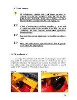
Page 26: ...ntenance operations must be shorter Take care that grease nipples on the machine are always clean After each maintenance operation check that all guards are fitted on the proper place 9 1 Oil level control Use always the same type of oil SAE 90 At changing oil unscrew the plug under the gearbox and let the oil off Use the hole on the top of gearbox for filling in For pouring in use a funnel Pour i...

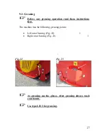
Page 27: ...on read these instructions first The machine has the following greasing points Left rotor bearing Fig 22 1 Right rotor bearing Fig 23 1 Fig 22 Fig 23 At greasing use the gloves After greasing always wash your hands Use type LIS 3 for greasing 5 ...

Page 28: ...ck If the nuts are tightened enough A wear and condition of working tools Belts and taper locks A condition of safe guards Oil level in the gearbox That any foreign parts are not stuck on the rotor shaft That the frame and the 3 point hitch are in good condition That all parts are greased well 3 On every 100 hours we recommend to Check and grease the PTO shaft 4 On every 12 months we recommend to ...

Page 29: ...season At the end of the season we recommend to clean the complete machine change eventual broken or worn parts tighten the bolts the belts grease the parts and oil the parts with damaged colour Put the machine on a dry and flat ground 9 6 Demolition when out of order If the machine is out of order all its parts that might cause dangers have to be made inoffensive Materials forming the machine tha...

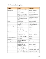
Page 30: ...amages and repair the machine Noise in the gearbox Lack of oil Fill till level Worn gears Replace Worn bearings Replace Vibrations Broken or worn flails Replace Unbalanced rotor Balance or replace Worn rotor bearings Replace Excessive backlash in joints Worn pins Replace Damaged bearings Dirty or ungreased bearings Clean and grease Violant impact on the ground when the machine is lowered Lower it ...

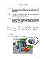
Page 31: ...ts min 7 years after the sael of the machine At ordering the spare parts always add the following details type of the machine serial number and year of the production All data are on the identification plate See the sample order below machine type Serial nr year Pos Part nr name pc f mower EURO MINI 333 2011 80 021216 gearbox 1 Servicing Tel 386 0 7 49 59 233 0 7 49 59 306 ...

Page 32: ...32 ...
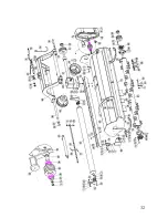
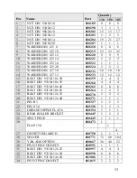
Page 33: ...12 010233 12 12 12 15 BOLT DIN 933 M 10x 30 010259 4 4 4 16 BOLT DIN 933 M 10x 35 010260 4 4 4 17 BOLT DIN 933 M 10x 45 010262 8 8 8 18 BOLT DIN 931 M 10x 65 010264 2 2 2 19 BOLT DIN 933 M 12x 35 010270 2 2 2 20 BOLT DIN 933 M 12x 40 010271 1 1 1 21 PIN R 3 010327 2 2 2 22 PIN fi 10 010328 3 3 3 23 GREASE NIPPLE FLAT 6 010394 1 1 1 24 REAR ROLLER BRCKET 010445 2 2 2 25 SPLIT PIN32 010449 1 1 1 26 ...

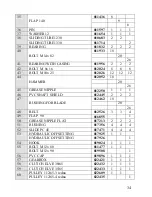
Page 34: ...012250 1 1 1 46 PVC SHAFT SHIELD 012445 2 2 2 47 BUSHING FOR BLADE 012462 18 20 26 48 BELT 012526 3 3 4 49 FLAP 90 016855 1 50 GREASE NIPPLE FLAT 017213 2 2 2 51 BUSHING 017356 4 4 4 52 SLIDE PC 45 017471 4 4 4 53 HYDRAULIC OFFSETTING 017925 1 1 HYDRAULIC OFFSETTING 017926 1 54 HOOK 019024 1 1 1 55 BOLT M 12x 80 011477 1 1 BOLT M 12x 90 019508 1 56 PVC CAP 019896 1 1 1 57 GEARBOX 022421 1 1 1 58 C...

Page 35: ...18 1 017436 1 022466 1 68 RING 022471 2 2 2 69 BRACKET 022474 1 1 1 70 PIN 022479 1 1 1 71 BOLT M 20x110 022482 1 1 1 72 BRACKET 022484 1 1 1 73 PLATE 022487 1 1 1 74 BELT SHIELD 022488 1 1 1 75 SKID LEFT 022500 1 1 1 76 SKID RIGHT 022504 1 1 1 77 FLAP BAR 010479 1 017427 1 022507 1 78 RUBBER GUARD 018049 1 018050 1 022509 1 79 RUBBER BAR 018045 1 018046 1 022510 1 80 BEARING GUARD 022511 1 1 1 81...

Page 36: ...36 INO BREŽICE d o o 8262 Krška vas 34 b Slovenija Tel 386 0 749 59 233 Fax 386 0 749 59 151 E mail ino inobrezice si www inobrezice com V 01 01 12 ...

Reviews: