Page 15
EN
Chapter 4 Assembly and function
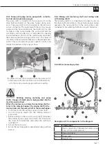
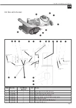
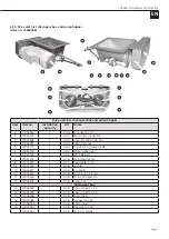
4.4.1.1 Frame with pull-out frame for pump hopper,
material hopper, water supply button and vibrator
The material hopper, the switching cabinet, the drive unit
for the mixer, the pull-out frame for the pump hopper incl.
the drive unit for the pump, the water measuring system
and the water supply button, the vibrator and the mixing
pipe are attached to the frame.
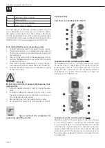
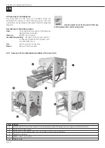
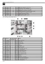
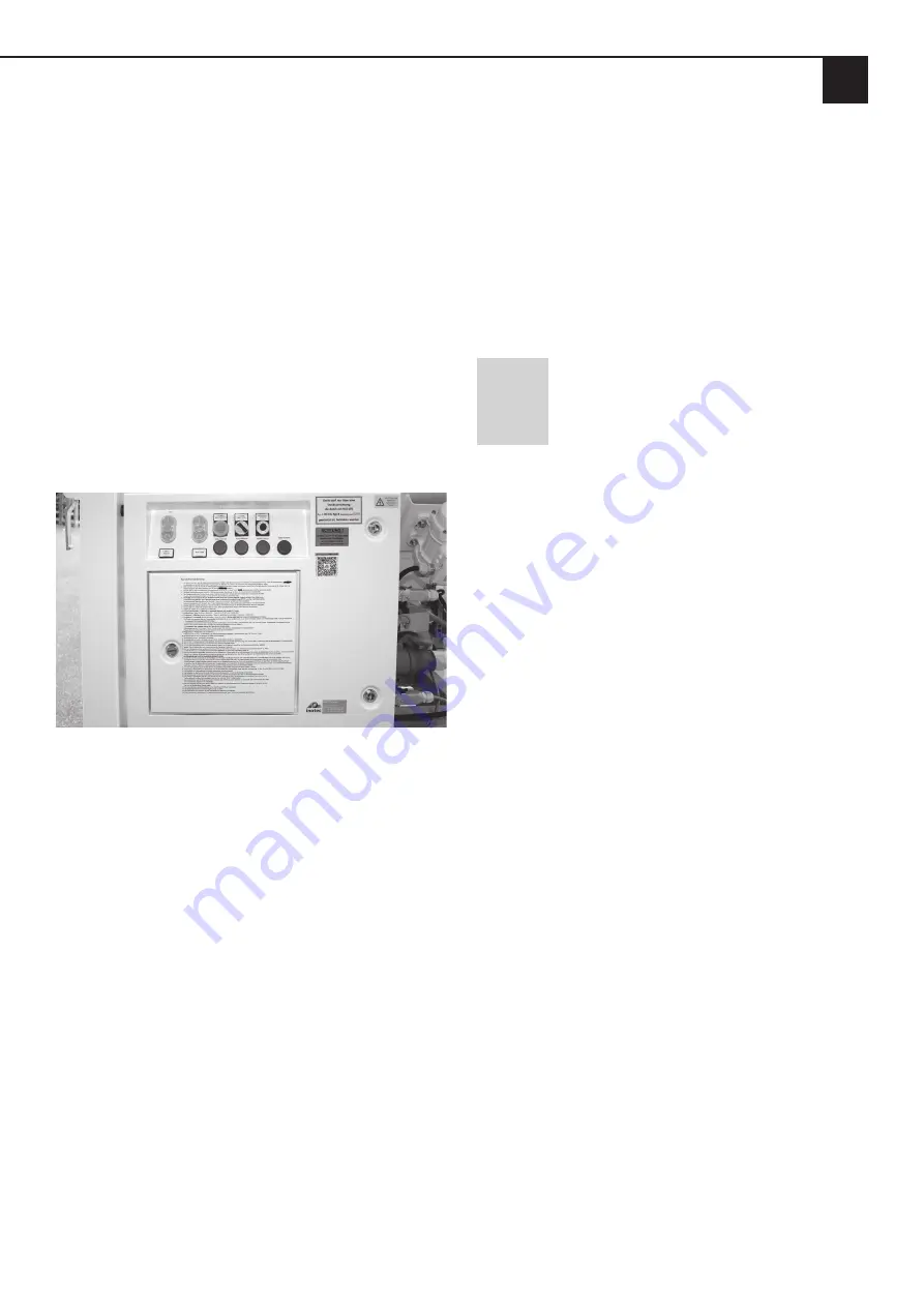
4.4.1.2 Switching cabinet
The switching cabinet is firmly connected to the frame of
the machine. All the necessary connections and controls for
operating the machine are located on the switching cabi-
net.
Connect the feed plug on the switching cabinet to the ex-
ternal power supply (400 V / 50 Hz). The cross-section of
the supply cable is at least 4.0 mm
2
at 400 V 3 PH! The small
silo inoCOMB Cabrio may only be operated with a permis-
sible RCD type B residual current circuit breaker (30 mA).
Switching cabinet, view from the front
4.4.1.3 Drive unit for the mixer
The mixer motor is firmly connected to the motor plate. For
cleaning purposes or to replace the metering shaft in the
material hopper, the unit can be folded away to the side.
The electrical connection plug of the motor is plugged into
the side of the switching cabinet.
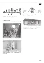
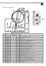
4.4.1.4 Water measuring system
The water measuring system is firmly connected to the
frame of the machine. The connection for the external wa-
ter supply line (min. 3/4") is located on the water measuring
unit. The water supply button is also attached to the frame.
The water flow button and the needle valve are used to
make a rough adjustment of the water supply on the water
flow meter.
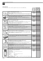
4.4.1.5 Mixing tube inoPOWER Mix with mixing shaft
and mixing tube cover
During transport, the mixing tube is dismantled and placed
in the pump hopper. This can be pushed under the material
hopper for transport. The opening for the mixing tube in
the material hopper is closed with a green cover. For opera-
tion, the green cover is removed and the mixing tube is at-
tached to the mixing tube holder with two eccentric locks.
The mixing shaft is pushed into the mixing tube together
with the mixing tube cover and is also fastened to the mix-
ing tube frame with two eccentric locks.
NOTE
Make sure that the mixing shaft is con-
nected to the metering shaft.
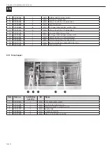
4.4.1.6 Drive unit for the feed pump, incl. chain gear
box and pump hopper
The pump motor is firmly connected to the chain gear box
and the pump hopper. The pump hopper contains the pump
shaft, which is connected to the pump unit (rotor/stator). A
level probe is also mounted in the pump hopper to monitor
the level of the material in the pump hopper.


