UM_INAP375R Revision 1.2_A1
Inova Semiconductors Confidential
Page 19 of 37
User Manual
4.0 Hardware Configurations
4.1 Power supply
4.1.1 12V Main Board supply
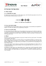
Normally the board is powered from a 12V DC voltage source. A DC/DC switcher generates 3.9V and 2.1V as
input to the different LDOs providing 3.3V and 1.8V.
Figure 4-1: 12 V Main Power Plug (RAPC722)
4.1.2 Low noise board supply
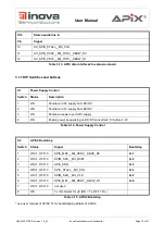
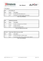
To support EMI measurements the DC/DC switchers, mentioned above, can be disabled by the dip switch S1.1
and S1.2. The LDO input voltages can be supplied directly through X1.
4.1.3 Power over APIX (PoA)
The AC-coupling of the serial APIX IOs opens the possibility to transmit power over the APIX serial data lines.
For details and consideration of PoA please see the application note AN202. The TX board provides a dedi-
cated 18V / 2A extreme low noise power supply to demonstrate this feature and allows to remotely power up
the RX application board.
4.2 Reset
After power up the board and especially the
μ
C requires a hardware reset for proper function. The hardware
reset is applied by pressing S3.
After hardware reset on S3 the
μ
C generates a board reset signal (
DIGITAL_RESET_N
) for all board compo-
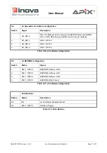
nents, excluding APIX2. By placing a 0 ohm resistor on R189 and removing R190 the board reset
(
DIGITAL_RESET_N
) can be coupled directly to the hardware reset generated from S3. (Bypassing the
μ
C
board reset generation)
Further, after hardware reset on S3 the
μ
C generates a reset signal (
APIX_RESET_N
) for APIX2, if JP8.1 is
connected with JP8.2. A manual APIX2 hardware reset can be generated when JP8.2 is pulled low, f.e. con-
necting JP8.2 with JP8.3.
ATTENTION: As APIX2 needs to be configured after reset, a manual reset on JP8.2 brings APIX2 in default
mode, according the bootstrap settings. The
μ
C does not handle the configuration of APIX2 in this case. To
avoid any collision on the interface between
μ
C and APIX2, S4.1 is required to be ON! Otherwise the board
can be damaged!

