9
INOVANCE TECHNOLOGY EUROPE GmbH
MD800 EtherCAT Starting Guide_EN_v1.1_20211109.docx
5
QUICK START COMMISSIONING
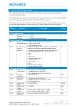
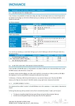
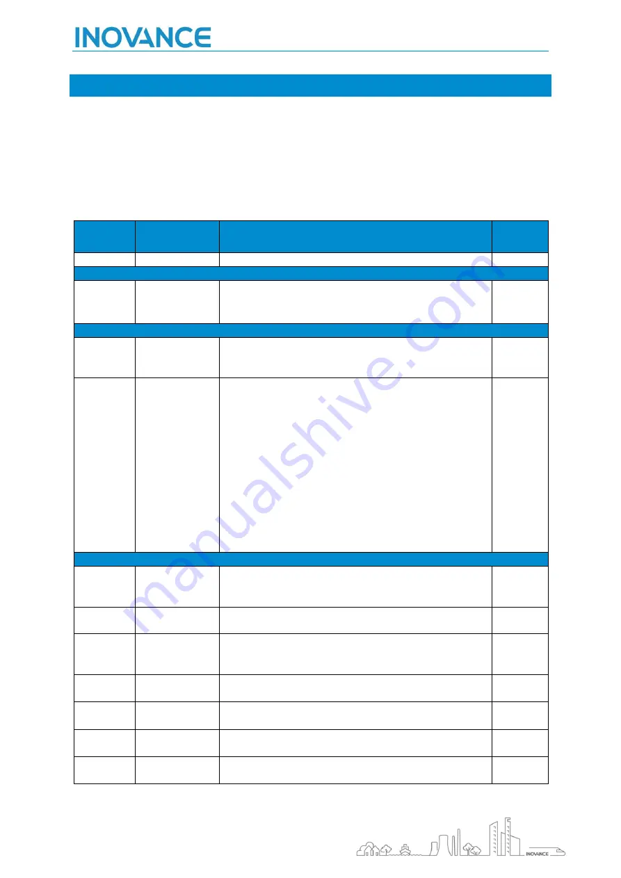
After installing the SI-ECAT card on the MD800 series AC drive, complete configuration to enable the
communication between them.
The following parameters must be set to enable normal communication between the SI-ECAT card and MD800
series AC drive and connect the SI-ECAT card to the EtherCAT fieldbus network.
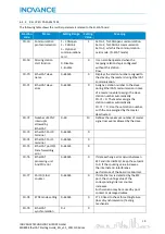
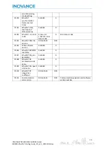
The table also shows the basic configuration of the single axis motor map and the different autotune modes.
For a more detailed description of the autotune process, consult the MD800 commissioning manual.
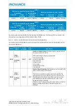
Parameter
Description
Setting Range
Value
Rectifier communication
FD-10
Communication
protocol
selection
1
:
CANopen
2
:
CANlink
3
:
Optional communications card
3
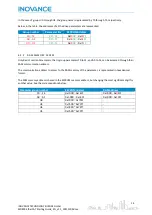
Inverter communication
F0-02
Command
source selection
0: External LCD panel/Commissioning software
1: Terminal I/O control
2: Communication control
2
F0-03
Main frequency
source X
selection
0: Digital setting (initial value F0-08 can be modified by
terminal UP/DOWN, non-retentive at power failure)
1: Digital setting (initial value F0-08 can be modified by
terminal UP/DOWN, retentive at power failure)
2: AI1
3: AI2
4: (Reserved)
5: Pulse reference (DIO1)
6: Multi-reference
7: Simple PLC
8: PID
9: Communication setting
10: Synchronization control
9
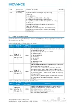
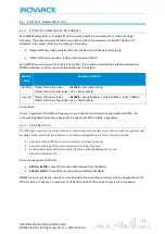
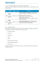
Inverter motor configuration
F0-01
1st motor
control mode
0: Sensorless vector control (SVC)
1: Feedback vector control (FVC)
2: Voltage/Frequency control (V/F control)
1
F0-10
Maximum
frequency
5.00 to 590.00 Hz
50Hz
F1-00
Motor type
selection
0: Common asynchronous motor
1: Variable frequency asynchronous motor
2: Synchronous motor
1
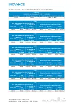
F1-01
Rated motor
power
0.1 to 1000.0 kW
0.55kW
F1-02
Rated motor
voltage
1 to 2000 V
380V
F1-03
Rated motor
current
0.01 A to 655.35 A (drive power ≤ 55 kW)
0.1 A to 6553.5 A (drive power > 55 kW)
1.3A
F1-04
Rated motor
frequency
0.01 Hz to maximum frequency (F0-10)
50Hz

