background image


31 

INOVANCE TECHNOLOGY EUROPE GmbH 
MD800 EtherCAT Starting Guide_EN_v1.1_20211109.docx 

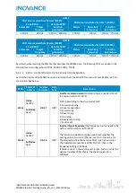
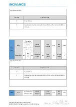
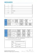
Accessibility  RW 

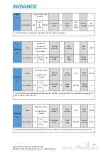
Can 

It 

map 

RPDO 

Correlation 

mode 

vl 

Data 

range 

0~65535 

factory 

setting  

20 

(1) F0-19 needs to set 1 or 2. If 0 is set, the calculation of acceleration and deceleration time will be 
inaccurate due to calculation error. 


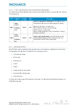
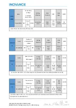
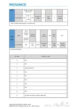
Indexes 

605Ah 

name 

 Fast shutdown 
mode selection 

Quick stop option 

code 

Setting 

effective 


data 

structure 

VAR 

data 
type 

Int16 

Accessibility  RW 

Can 

It 

map 

NO 

Correlation 

mode 

ALL 

Data 

range 

0~2 

factory 

setting  

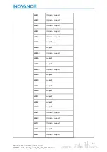
  (1) Setpoint definition 


Set value 

Shutdown mode 

Coast to stop 

Deceleration stop: the deceleration time is f0-18, i.e. the set time of 6049h in 
VL mode 

For emergency stop, the deceleration time is the time set by f8-60 


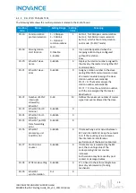
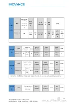
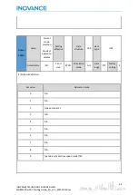
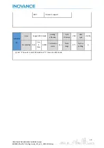
Indexes 

605Bh 

name 

 Stop mode 

selection 

Shut down option 

code 

Setting 

effective 


data 

structure 

VAR 

data 
type 

Int16 

Accessibility  RW 

Can 

It 

map 

NO 

Correlation 

mode 

ALL 

Data 

range 

0~1 

factory 

setting  

Summary of Contents for EtherCAT MD800

Page 1: ...2021 INOVANCE TECHNOLOGY EUROPE V1 1 MD800 EtherCAT Starting Guide...

Page 2: ...Communication Addresses 13 6 2 1 EEPROM memory access 13 6 2 2 RAM memory access 14 6 3 ETHERCAT communication 15 6 3 1 Ethercat communication address 15 6 3 2 PDO Area data 15 6 3 3 SDO Mailbox data...

Page 3: ...MD800 EtherCAT Starting Guide_EN_v1 1_20211109 docx 8 4 1 Drives digital I O configurration 60 9 PC Tools 69 9 1 InoDriverShop 69 9 2 MD800 firmware update 72 9 2 1 Using InoLoader software 73 9 2 2 U...

Page 4: ...SI ECAT card Software InoDriverShop for AC drives 3 6 1 16 Info MD800 EtherCAT communication procedure 2 PURPOSE OF THIS DOCUMENT The purpose of this document is to facilitate the commissioning of Eth...

Page 5: ...between SI ECAT rectifier and inverter units have a communication cycle of 40ms NOTE The SI ECAT supports the CiA402 Velocity and Cyclic Synchronous Velocity CSV modes which are suitable for the MD800...

Page 6: ...ght is completely extinguished before installation After the SI ECAT card is inserted into the inverter please check whether it is securely inserted to prevent the signal socket between the boards fro...

Page 7: ...must be connected correctly The Cat5e shielded twisted pair STP network cable must be used for ensuring stability To improve the anti interference capability of communication it is recommended to ins...

Page 8: ...one Steady green EtherCAT state machine state OP run None EC ERR Red light off EtherCAT communication is trouble free None Red light is always on EtherCAT communication is faulty Check the fault code...

Page 9: ...the Ethernet master station properly With relevant communication setting the communication with the EtherCAT master station can be realized thus realizing the networking function of the AC drive The...

Page 10: ...panel Commissioning software 1 Terminal I O control 2 Communication control 2 F0 03 Main frequency source X selection 0 Digital setting initial value F0 08 can be modified by terminal UP DOWN non ret...

Page 11: ...source needs to be set to communication F0 02 2 0 Stop according to the stop mode F6 10 1 Forward running 2 Reverse operation 3 Forward jog 4 Reverse jog 5 Free stop 6 Decelerate to stop 7 Fault rese...

Page 12: ...500 RPM Acceleration from 0 to 1500 RPM in 2 5 seconds Deceleration from 1500 to 0 RPM in 5 seconds Index hex Sub index hex Drive Parameter Name Unit Value FD 11 CANopen402 protocol 1 Enabled F0 19 Ac...

Page 13: ...rol are performed by the drive The following table shows the necessary settings to work with the Cyclic Synchronous Mode of the CiA402 standard Index hex Sub index hex Drive Parameter Name Unit Value...

Page 14: ...e the sample below Group Description Group number Parameter ID Parameter Name F0 Basic Power Supply Unit F0 16 F0 16 AF Process Data Address Mapping AF 00 AF 00 U0 Monitoring Parameters U0 35 U0 35 6...

Page 15: ...MEMORY ACCESS Only Basic Function Parameters that is group parameters F0 to FE and A0 to AF can be accessed through their RAM communication address The communication address to access to the RAM memor...

Page 16: ...Number Axis Number 0x1 0x800 Object Dictionary Sub Index 0x1 Parameter ID For example For axis 2 parameter F0 03 Main frequency source X selection and communication address 0xF003 the corresponding o...

Page 17: ...O2 TPDO3 TPDO16 AXIS 3 PDO area received from Master 1603h PDO area transmitted by AXIS 3 1A03h Fixed RPDO Variable RPDO Command Target Frequency Function parameters Status Operating Frequency Functio...

Page 18: ...MASTER Each of the devices of the MD800 receives information from the EtherCAT master in its own RPDO area This area is described below RPDO EtherCAT address Inverter Parameter Data Type Description...

Page 19: ...ing Bit2 0 no fault 1 inverter fault Bit3 0 running frequency is not up to standard 1 running frequency is reached TPDO2 Index 0x2070 SubIndex 0x1 U0 68 UINT Inverter operating frequency unit 0 01Hz R...

Page 20: ...nable to assign the slave station number automatically FD 71 0 The master assigns the station number automatically FD 71 0 Use the set station number with the one assigned by the master deactivated FD...

Page 21: ...1 0xFFFF Error status code 0 Error status code FD 83 EtherCAT XML file version 0 00 655 35 0 00 FD 84 FPGA software version 0 65535 0 FD 86 EtherCAT EEPROM read time 0 65535 0 FD 87 EtherCAT DC gain p...

Page 22: ...alue Range 6040 00 Control word RW Uint16 0 65535 6041 00 Status word RO Uint16 0 65535 6060 00 Modes of operation RW Int8 0 9 6061 00 Modes of operation display RO Int8 0 9 6042 00 vl target velocity...

Page 23: ...ration RW Int8 0 9 6061 00 Modes of operation display RO Int8 0 9 60FF 00 Target velocity RW Int32 RPM 231 231 1 60B1 00 Velocity Offset RO Int32 RPM 231 231 1 607E 00 Polarity RO Uint8 0 255 606C 00...

Page 24: ...elocity max amount U4 11 0x6046 02 low byte 0 65535 U4 12 0x6048 01 high byte 1 65535 unit RPM vl velocity acceleration Delta speed U4 13 0x6048 01 low byte U4 14 0x6048 02 0 65536 unit s vl velocity...

Page 25: ...quirements of DS402 The read fault code is the fault code defined by the manufacturer The upper 8 bits are the main fault code and the lower 8 bits are the fault subcode For specific meaning please re...

Page 26: ...acturer defined Bit8 15 has no function defined at present Indexes 6041h name Status word Status word Setting effective data structure VAR data type Uint16 Accessibility RO Can It map TPDO Correlation...

Page 27: ...alue binary describe Xxxx xxxx x0xx 0000 Not ready Not ready to switch on Xxxx xxxx x1xx 0000 Start failed switch on disabled Xxxx xxxx x01x 0001 Ready Ready to switch on Xxxx xxxx x01x 0011 Start Swi...

Page 28: ...port higher speed setting Indexes 6043h name Speed setting vl velocity demand Setting effective data structure VAR data type int16 Access ibility RO Can It map RPDO Correlation mode vl Data range 3276...

Page 29: ...a range factory setting 2 Subindex 1h name Minimum speed vl velocity min amount Setting effective data structure VAR data type Uint32 Accessibility RW Can It map RPDO Correlation mode vl Data range 0...

Page 30: ...O Correlation mode vl Data range factory setting 2 Subindex 1h name Speed variation Delta speed Setting effective data structure VAR data type Uint32 Accessibility RW Can It map RPDO Correlation mode...

Page 31: ...ber of decelerator indexes Setting effective data structure data type Uint8 Accessibility RO Can It map NO Correlation mode vl Data range factory setting 2 Subindex 1h name Speed variation Delta speed...

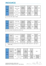
Page 32: ...top option code Setting effective data structure VAR data type Int16 Accessibility RW Can It map NO Correlation mode ALL Data range 0 2 factory setting 1 1 Setpoint definition Set value Shutdown mode...

Page 33: ...ame Off enable shutdown mode selection Disable operation option code Setting effective data structure VAR data type Int16 Accessibility RW Can It map NO Correlation mode ALL Data range 0 1 factory set...

Page 34: ...setting 0 1 The current value supports 0 coast to stop Indexes 6060h name Mode selection setting Mode of operation Setting effective data structure VAR data type Int8 Accessibility RW Can It map RPDO...

Page 35: ...e selection Mode of operation display Setting effective data structure VAR data type Int8 Accessibility RO Can It map RPDO Correlation mode ALL Data range 0 9 factory setting 9 1 Setpoint definition S...

Page 36: ...ccessibility RO Can It map TPDO Correlation mode ALL Data range unit 0 1 factory setting 1 The unit is based on the rated torque of the motor Indexes 607Eh name Command polarity Polarity Setting effec...
Page 37: ...VAR data type Int32 Accessibility RW Can It map YES Correlation mode CSV Data range 231 231 1 unit RPM factory setting 0 Indexes 6502h name Support mode Supported drive modes Setting effective data st...

Page 38: ...name Does the object dictionary support power down saving Setting effective data structure VAR data type Uint16 Accessibility RW Can It map RPDO Correlation mode ALL Data range 0 1 factory setting 0 1...

Page 39: ...4 It doesn t support 6046 0 It doesn t support 6046 1 support 6046 2 support 6048 0 It doesn t support 6048 1 support 6048 2 support 6049 0 It doesn t support 6049 1 support 6049 2 support 605A suppor...

Page 40: ..._20211109 docx 60FF It doesn t support Subindex Ch name Support 402 mode Setting effective data structure VAR data type Uint16 Accessibility RW Can it map RPDO Correlation mode ALL Data range 0 1 fact...

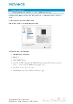
Page 41: ...the software and create an AM600 project Select AM600 CPU1608TP as shown in the following figure 2 Add the MD500 AC drive slave station 1 Open the network configuration 2 Select CPU 3 Enable EtherCAT...

Page 42: ...PDO Setting tab 3 Enable Input Output PDOs related to each axis The MD800 can handle up to 8 axes 4 Select Input Output PDOs 5 Click on Add button 6 Select the required PDO and add to PDO settings lis...

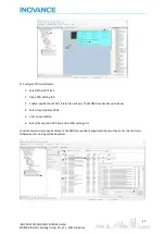
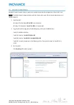
Page 43: ...apters may not support EtherCAT 1 Install TwinCAT Windows XP system tcat_2110_2230 is recommended Windows 7 32 bit system tcat_2110_2248 is recommended 2 Copy the EtherCAT configuration file MD800_9Ax...

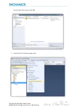
Page 44: ...43 INOVANCE TECHNOLOGY EUROPE GmbH MD800 EtherCAT Starting Guide_EN_v1 1_20211109 docx Select TwinCAT XAE Project and click OK 4 Install the TwinCAT network adapter driver...

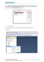
Page 45: ...ices In the displayed dialog box select the local network adapter in Incompatible devices and click Install After installation the installed network adapter is displayed in Installed and ready to use...

Page 46: ...NOVANCE TECHNOLOGY EUROPE GmbH MD800 EtherCAT Starting Guide_EN_v1 1_20211109 docx The following message appears Click OK Select EtherCAT device and click OK Click Yes Select NC configuration and clic...

Page 47: ...46 INOVANCE TECHNOLOGY EUROPE GmbH MD800 EtherCAT Starting Guide_EN_v1 1_20211109 docx...

Page 48: ...47 INOVANCE TECHNOLOGY EUROPE GmbH MD800 EtherCAT Starting Guide_EN_v1 1_20211109 docx Click No Now the equipment search is complete as shown in the following figure...

Page 49: ...axis 2 axis 3 etc PDO inputs 5 Select the corresponding index to configure the PDOs 6 The first two items are set to TPDO by default and cannot be changed Right click at the position indicated by ste...

Page 50: ...49 INOVANCE TECHNOLOGY EUROPE GmbH MD800 EtherCAT Starting Guide_EN_v1 1_20211109 docx...

Page 51: ...1 axis 2 axis 3 etc PDO outputs 11 Select the corresponding index to configure the PDOs 12 The first two items are set to RPDO by default and cannot be changed Right click at the position indicated by...

Page 52: ...docx 2 View the SDO data list After the OP state is activated you can view real time data in the SDO data list or double click the object dictionary to modify the SDO data 3 Activate the configuratio...

Page 53: ...52 INOVANCE TECHNOLOGY EUROPE GmbH MD800 EtherCAT Starting Guide_EN_v1 1_20211109 docx Click OK...

Page 54: ...NOLOGY EUROPE GmbH MD800 EtherCAT Starting Guide_EN_v1 1_20211109 docx Click OK to enter the OP state 4 Control the AC drive through PDO Write corresponding values through the configured RPDO to contr...

Page 55: ...he first level menu Enter Go to the next screen Confirmation of mode parameter and set value Multi axis switch key To switch between multiple axes rectifier is selected by default Increment key Change...

Page 56: ...te Flashing operated by rectifier keyboard ERR red Alarm indicator Steady on The device is malfunctioning Off The device is normal Flashing The device has an alarm 8 3 RECTIFIER MODULE DISPLAY Keypad...

Page 57: ...AMETERS Parameter Parameter name Default Value Setting Range Description F7 01 MF K key function selection 0 0 MF K is invalid 1 Switch between terminal command channel or communication command 2 Forw...

Page 58: ...key stops The STOP button on the operation panel is the stop reset button set STOP behavior by this parameter The function of the key 0 Only in the keyboard operation mode the stop function of the STO...

Page 59: ...d set it in F7 04 Pressing the shift key the configured parameters can be displayed F7 05 Stop display parameters 51 BIT00 set frequency Hz BIT01 bus voltage V BIT02 DI input status BIT03 DO output st...

Page 60: ...ime F7 09 cumulative power on time F7 12 The cumulative power generation F7 13 and cumulative power consumption F7 14 will not recover 2 Clear record information Clear the inverter fault record inform...

Page 61: ...selection 0 63 See table below Select the function of the input terminal F4 02 DI2 hardware source selection See function code F4 00 setting range Select the source of the input terminal F4 03 DI2 ter...

Page 62: ...s used to control the start and stop of the inverter and the other is used to control the running direction 2 Three wire 1 Three wire mode 1 access 3 DI terminals one is used to control the start and...

Page 63: ...gh level active 1 active low Ten 0 High level active 1 active low hundreds 0 High level active 1 active low Thousands 0 reserved Ten thousand 0 reserved Set the effective mode of DI1 DI8 terminal thro...

Page 64: ...A6 15 There are 2 points on AI curve 1 3 namely the minimum input point and the maximum input point F4 31 corresponds to the x axis of the minimum input point of AI curve 1 that is the minimum modulu...

Page 65: ...e maximum analog input current F4 42 AI curve 3 maximum input corresponding setting 100 0 100 0 The y axis corresponding to the maximum input point of AI curve 3 is the set value corresponding to the...

Page 66: ...t the run command through the terminal set the parameter F4 17 terminal command mode to 2 Three wire type 1 or 3 Three wire type 2 the terminal function should be set to this function 4 Forward jog FJ...

Page 67: ...the terminal of this function is selected Change to communication control if the communication control operation command is used the system will switch to terminal control when the terminal that sele...

Page 68: ...mmand selection is the operation panel F0 02 0 the inverter will stop 42 42 External parking terminal 2 In any running command mode panel control terminal control communication control the inverter de...

Page 69: ...to switch between two wire and three wire control If F4 17 is set to 0 two wire type 1 when the terminal of this function is valid switch to three wire type 1 If F4 17 is set to 1 two wire type 2 when...

Page 70: ...ons communication with the InoDriverShop diagnostic and monitoring software and firmware update 9 1 INODRIVERSHOP InoDriverShop is the software for windows platforms that allows diagnosis and monitori...

Page 71: ...x 2 Select Online the MD800 drive and click on the next button 3 The software will detect the connected modules and shows a list The software detects the different modules and displays them in a list...

Page 72: ...TECHNOLOGY EUROPE GmbH MD800 EtherCAT Starting Guide_EN_v1 1_20211109 docx 4 The detected modules are shown in the project tree from where you can access the list of parameters or the control panel of...

Page 73: ...tional communication modules This section explains the procedure and the different methods to carry out this task The following table shows the parameters that indicate the firmware version of each mo...

Page 74: ...and a computer to run the software Connect the USB C cable to the laptop and the MD800 and follow the below procedure Start the InoLoader software and select the USB interface as the communication po...

Page 75: ...is necessary a USB Mini b and RJ45 cable The USB cable is for copy the firmware file to the SOP 20 memory The RJ45 cable is for communicate SOP 20 with the MD800 drive port To update the firmware fol...

Page 76: ...LOGY EUROPE GmbH MD800 EtherCAT Starting Guide_EN_v1 1_20211109 docx Select Authority Select Login Enter administrator password 37421 Click button back to return to main menu Select System control Sel...

Page 77: ..._v1 1_20211109 docx Select firmware file Click OK Select device address Rectifier 16 Axis 1 1 Axis 2 2 Axis 8 8 Upper option module 14 Lower option module 15 Select baud rate parameter FD 00 Modbus ba...

Page 78: ...1_20211109 docx If the process finish without any problem this message appears 10 NOTES If FD 10 3 the RUN ERR led flashes quickly and the rectifier gets the trip E16 77 Change the parameter FD 10 to...

Reviews: