3 Keypad and Display
3
- 24 -
Chapter 3 Operation and Display
3.1 Introduction to Keypad
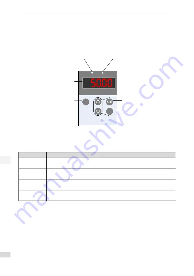
Figure 3-1 Diagram of the keypad
.
MODE
SET
RUN
ERR
Fault indicator
RUN indicator
Data display
MODE key
SET key
UP key
DOWN key
SHIFT key
The keypad on the servo drive consists of the 5-digit 7-segment LEDs and keys. The keypad is used for
display, parameter setting, user password setting and general functions operations. When the keypad is
used for parameter setting, the functions of the keys are described as follows.
Table 3-1 Functions of keys on the keypad
Key Name
Function Description
MODE
Switch between all modes.
Return to the upper-level menu.
UP
Increase the number indicated by the blinking digit.
DOWN
Decrease the number indicated by the blinking digit.
SHIFT
Shift the blinking digit.
View the high digits of the number consisting of more than 5 digits.
SET
Switch to the next-level menu.
Execute commands such as storing parameter setting value.
Summary of Contents for IS650P Series
Page 1: ......
Page 101: ...100 Revision History Date Version Change Description March 2017 A00 First issue...
Page 102: ......


