6. Description of Parameters
- 134 -
6
6.2.4 Command Frequency Reference Setting Channel
,WLVSRVVLEOHWRFRQWURO¿QDOIUHTXHQF\UHIHUHQFHWKURXJKFRPPDQGVRXUFHIUHTXHQF\UHIHUHQFH
setting channel.
Figure 6-29 Command main frequency reference setting channel
0
1
2
3
4
5
6
7
8
9
Final
frequency
reference
Units position
Tens position
F0-02
Hundreds
position
Digital setting
Pulse reference
Multi- reference
Simple PLC
PID reference
Serial comms.
Operating
panel
Terminal I/O
Serial
comms.
AI1
AI2
AI3
No function
0
1
2
F0-27
Units position
Tens position
Hundreds position
Setting
Output
0
0
0
000
0
0
1
0
100
1
0
9
0
900
9
..
.
..
.
..
.
..
.
..
.
Units position
Tens position
Hundreds position
Output
0
0
0
000
0
0
0
1
001
1
0
0
9
009
9
...
...
...
...
...
Units position
Tens position
Hundreds position
Setting
Output
0
0
0
000
0
1
0
0
010
1
9
0
9
090
9
..
.
..
.
..
.
..
.
..
.
Setting
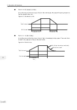
When a command frequency reference setting channel is used to control final
frequency reference, both main and auxiliary frequency reference setting channels (F0-03 and
F0-04) become ineffective.
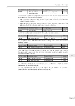
Function Code
Parameter Name
Setting Range
Default
F0-27
Command
frequency source
Terminal c frequency source
The same as that of units position
Operating panel + frequency source
0: Not binding
1: Digital setting
2: AI1
3: AI2
4: AI3
5: Pulse reference (DI5)
6: Multi-reference
7: Simple PLC
8: PID reference
9: Serial comms.
Serial comms. + frequency source
The same as that of units position
000
Summary of Contents for MD290 Series
Page 1: ......
Page 79: ...3 Electrical Installation 78 3 ...
Page 80: ...4 Operating Panel Keypad Display 4 1 Introduction 80 4 2 Inbuilt LED Operating Panel 80 ...
Page 92: ...5 Quick Setup 5 1 Get Familiar With Operating Panel 92 5 2 Setup Flowchart 93 ...
Page 227: ...7 Interfaces and Communication 226 7 ...
Page 285: ...10 Troubleshooting 284 11 ...
Page 349: ......
Page 350: ......


