6. Description of Parameters
- 182 -
6
Function Code
Parameter Name
Setting Range
Default
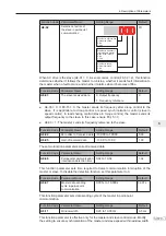
F4-39
DI active mode
selection 2
DI7 active mode:
0: High level active
1: Low level active
DI6 active mode:
0: High level active
1: Low level active
DI8 active mode:
0: High level active
1: Low level active
DI10 active mode:
0: High level active
1: Low level active
DI9 active mode:
0: High level active
1: Low level active
00000
These two function parameters set active mode of DI terminals.
Ɣ
0: High level active
If a high level voltage is applied to DI terminal, the DI signal will be seen as active. That is,
the DI terminal becomes active when being connected with COM, and inactive when being
disconnected from COM.
Ɣ
1: Low level active
If a low level voltage is applied to DI terminal, the DI signal will be seen as active. That is, the
DI terminal becomes active when being disconnected from COM, and inactive when being
connected with COM.
6.9.2 Function of DO Terminals
The drive provides a digital output (DO) terminal, an analog output (AO) terminal, a relay terminal
and an FM terminal (either high-speed pulse output or open-collector output).
Extra AO terminal (AO2), relay terminal (relay2) and DO terminal (DO2) are provided by the I/O
extension card.
Function Code
Parameter Name
Setting Range
Default
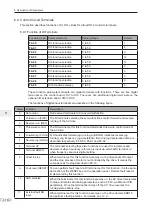
F5-00
FM terminal output mode
0: Pulse output (FMP) 1:
Digital output (FMR)
0
This function parameter is a programmable multiplexing terminal and determines whether FM
terminal is high-speed pulse output (FMP) or open-collector output (FMR). When used for high-
speed pulse output, max. output frequency is 100 kHz. For details, see the description of
F6-05
.
Function Code
Parameter Name
Setting Range
Default
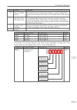
F5-01
FMR function selection
0 to 41
0
F5-02
Relay (T/A-T/B-T/C) function selection
0 to 41
2
F5-03
Extension card relay (P/A-P/B-P/C)
function selection
0 to 41
0
F5-04
DO1 function selection
0 to 41
1
F5-05
Extension card DO2 function selection
0 to 41
4
Summary of Contents for MD290 Series
Page 1: ......
Page 79: ...3 Electrical Installation 78 3 ...
Page 80: ...4 Operating Panel Keypad Display 4 1 Introduction 80 4 2 Inbuilt LED Operating Panel 80 ...
Page 92: ...5 Quick Setup 5 1 Get Familiar With Operating Panel 92 5 2 Setup Flowchart 93 ...
Page 227: ...7 Interfaces and Communication 226 7 ...
Page 285: ...10 Troubleshooting 284 11 ...
Page 349: ......
Page 350: ......


