3. Electrical Installation
- 49 -
3
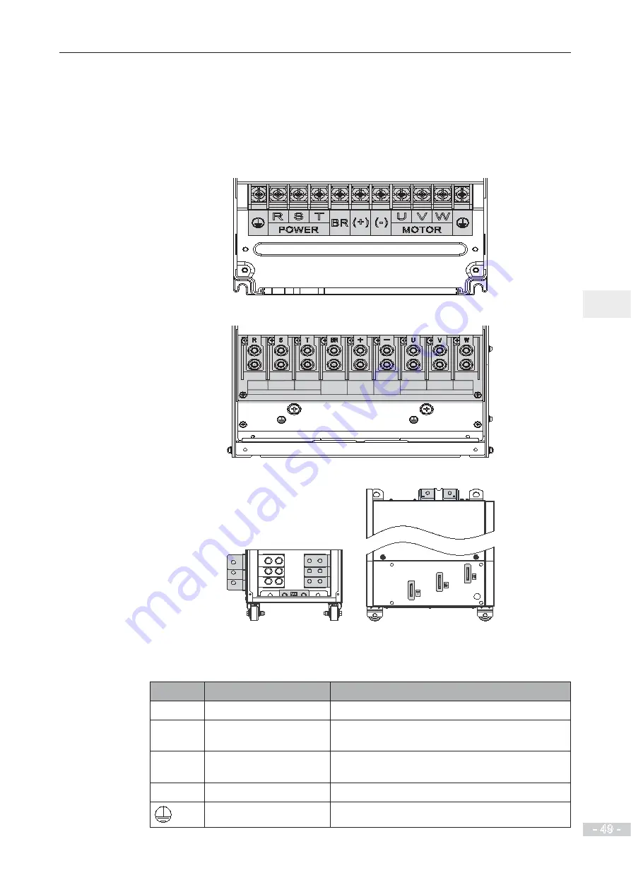
3.2 Main Circuit Wiring
3.2.1 Main Circuit Terminals
Ƶ
Terminal Arrangement
MD29018.5G/22P to MD29037G/45P
MD290T45G/55P to MD290132G/160P
R
S
POWER
T
BR
(+)
(-)
V
U
W
MOTOR
MD290T200G
to
MD290T450G and MD290T220P
to
MD290T500P
U
V
W
Ƶ
Terminal Function
Table 3-1 Description of input and output connections of the drive
Terminal
Name
Description
R, S, T
Three-phase supply input
Connected to three-phase power supply.
(+), (-)
DC bus terminals
Connected to external braking unit (MDBUN) with
AC drive units of 90 kW and above.
(+), BR
Braking resistor
connection
Connected to external braking resistor for AC drive
units of 75 kW and below.
U, V, W
AC drive outputs
Connected to a three-phase motor.
Ground (PE)
Grounding connection.
Summary of Contents for MD290 Series
Page 1: ......
Page 79: ...3 Electrical Installation 78 3 ...
Page 80: ...4 Operating Panel Keypad Display 4 1 Introduction 80 4 2 Inbuilt LED Operating Panel 80 ...
Page 92: ...5 Quick Setup 5 1 Get Familiar With Operating Panel 92 5 2 Setup Flowchart 93 ...
Page 227: ...7 Interfaces and Communication 226 7 ...
Page 285: ...10 Troubleshooting 284 11 ...
Page 349: ......
Page 350: ......


