MD320/MD320N User Manual Appendix
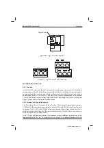
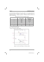
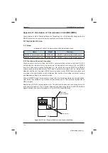
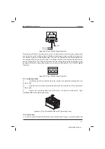
2. Schematic Diagram for Frequency Division Interface
Frequency division
Schematic Diagram
$SSHQGL[$)LJ6FKHPDWLF'LDJUDPIRU)UHTXHQF\'LYLVLRQ,QWHUIDFH
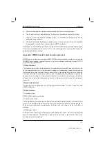
A.2.4 Precautions
1.
7KH3*FDUGVLJQDOFDEOHVDQGWKHSRZHUFDEOHVVKDOOEHDUUDQJHGVHSDUDWHO\DQGSDUDOOHO
wiring is not allowed;
2.
7RDYRLGLQWHUIHUHQFHVRQWKHHQFRGHUVLJQDOSOHDVHVHOHFWWKHVKLHOGHGFDEOHDVWKH3*
card signal cable;
3.
The shielding layer of the shielded cable of the encoder shall be earthed (e.g. the PE end
of inverter) and must be earthed at single end so as to avoid interferences on the signal;
4.
The length of shielded cable of the encoder shall be less than 80 meters.
,IWKHIUHTXHQF\GLYLVLRQRXWSXWRIWKH3*FDUGLVFRQQHFWHGWRH[WHUQDOXVHUSRZHUVXSSO\
WKHYROWDJHVKDOOEHOHVVWKDQ9RULWZLOOGDPDJHWKH3*FDUG
A.3 Application Connection
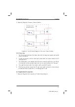
1. Schematic Diagram for the Connection of Collector Output Encoder
efesotomasyon.com
Summary of Contents for MD320 Series
Page 9: ...z G Gw efesotomasyon com...
Page 16: ...Safety and Precautions MD320 MD320N User Manual efesotomasyon com...
Page 17: ...w Gp efesotomasyon com...
Page 40: ...Product Information MD320 MD320N User Manual efesotomasyon com...
Page 41: ...t G Gl Gp efesotomasyon com...
Page 59: ...v G Gk efesotomasyon com...
Page 67: ...m Gw G efesotomasyon com...
Page 93: ...w Gk efesotomasyon com...
Page 154: ...Parameter Description MD320 MD320N User Manual efesotomasyon com...
Page 155: ...ltjGn efesotomasyon com...
Page 159: ...m Gk G Gz efesotomasyon com...
Page 175: ...h efesotomasyon com...


