2 Installation
- 34 -
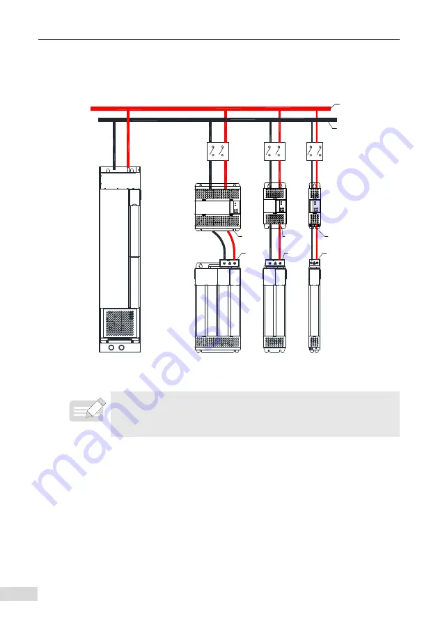
2.2.4 Installation of the DC Soft Charge Unit
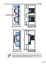
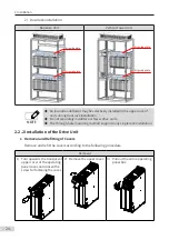
The following figure shows the diagram of using INOV-SU-30, INOV-SU-60, INOV-SU-100,
INOV-SU-170 DC soft charge units in conjunction with the MD810 series drive unit.
Power
supply
unit
DC soft
charge unit
Drive unit
DC
breaker
Positive bus
Negative bus
200 mm wide
100 mm wide
50 mm wide
Ejector
header
Ejector
header
Ejector
header
45
–75
kW
11
–37
kW
1.5
–7
.5 kW
RUN
ERR
RUN
ERR
RUN
ERR
DC
breaker
DC
breaker
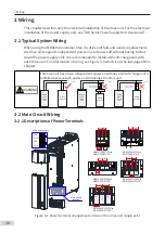
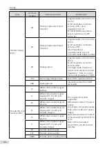
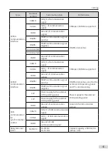
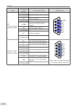
Figure 2-6 INOV-SU-30/INOV-SU-60/INOV-SU-100/INOV-SU-170 DC soft charge unit installation
NOTE
◆
Pay attention to the connection of the DC breaker in the preceding figure.
■
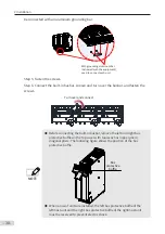
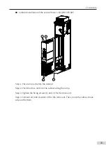
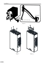
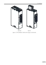
HST-6004, HST-7004, and drive unit installation procedure (take HST-6004 as an
example)
1)
As shown in figure a, remove the two M6 screws in the front side of HST-6004.
2)
Rotate the front side assembly upward, and then take it out as shown in figure b.
3) Disassemble the HST-6004 functional assembly into two parts, figure c is the HST
-6004 functional part, and figure d is the base.
4)
Connect the cable to the DC soft charge unit as shown in figure e.
5)
As shown in figure f, remove the four M4 screws on the top end of HST-6004.

