3 Wiring
- 48 -
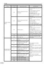
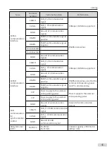
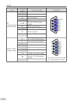
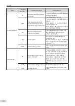
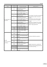
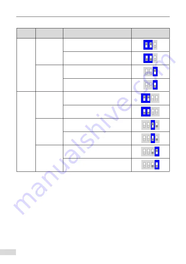
Table 3-4 Definition of DIP switches (single-axis)
Terminal
Symbol
Terminal Name
Function Description
DIP Switch Position
S1
CAN1
termination
resistor
selection
Connect the termination resistor when
switches 1 and 2 are turned on.
ON
1 2
3
Connect no termination resistor when
switches 1 and 2 are turned off.
ON
1 2
3
AI1 function
selection
PT100/PT1000 temperature detection
when switch 3 is turned on.
ON
1 2
3
Analog input when switch 3 is turned off.
ON
1 2
3
S2
C485
termination
resistor
selection
Connect the termination resistor when
switches 1 and 2 are turned on.
ON
1 2
3 4
Connect no termination resistor when
switches 1 and 2 are turned off.
ON
1 2
3 4
CAN2
termination
resistor
selection
Connect the termination resistor when
switch 3 is turned on.
ON
1 2
3 4
Connect no termination resistor when
switch 3 is turned off.
ON
1 2
3 4
PG interface 5 V
and 15 V power
supply selection
5 V power supply when switch 4 is turned
on.
ON
1 2
3 4
15 V power supply when switch 4 is turned
off.
ON
1 2
3 4


