— 13 —
PROGRAM LINE OUTPUTS
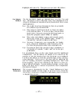
DAVID IV digital and analog line outputs are available simulta-
neously and may independently be adjusted in level and as-
signed the characteristic selected in the
Setup / Audio Output
menu (Page 37).
Line outputs may individually be set for a 20kHz flat character-
istic for digital radio, streaming, or other flat-power-bandwidth
applications. Alternatively, an FM mode is included for feeding
an FM exciter that has a built-in stereo generator, in which case
the outputs may assume a pre-emphasized or a normalized
(flat) frequency characteristic. Both FM options have full bene-
fit of independent HF limiting to protect the pre-emphasis
curve.
AES Digital
Line Output
The male XLR connector labeled
AES DIGITAL OUTPUT
is a bal-
anced, transformer-coupled digital stereo program output con-
forming to the AES3 (AES/EBU) specification. This is a 24-bit
output at a sampling rate that may be set to 32kHz, 44.1kHz,
48kHz or 96kHz. Sampling rate selection is made under the
Setup / Sample Rate Converter
menu (Page 35). The output sam-
pling rate may also be locked to the input sampling rate when
the DAVID IV
is fed from a digital program source.
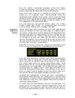
The digital output level shown below the slider control corre-
sponds to program peaks that have been limited to 100% modu-
lation. The output level may be adjusted between 0dBFS (digi-
tal full-scale) and –20dBFS.
Analog
Line Outputs
Male XLR left- and right-channel
ANALOG OUTPUTS
on the rear
panel are electronically-balanced. This means that they are
ground-referenced
and are
not
transformer-coupled.
Analog line outputs may be adjusted to any level between
–10dBu and +24dBu. The dBu levels shown below the slider
control represent the
unloaded
output level for 100%-mod-
ulation peaks. The outputs have a resistive source impedance
of 200 ohms; that is, there is a 100-ohm ‘buildout’ resistor in
each leg. When feeding a 600-ohm load, the actual dBm level
will be 2.5dB below the
Analog Level
shown under the slider.
Unbalanced
Operation
Should you have need to connect the analog line outputs of the
DAVID IV to consumer-grade, unbalanced inputs, connect the
center conductor of the shielded output lead to Pin 2 of the
XLR connector, and the shield to Pin 1. Leave Pin 3 floating
(unconnected). Be aware that the actual line level will be 6dB
lower than the
Analog Level
shown in the
Setup
/
Audio Output
menu as only one side of the bridge-configuration output am-
plifier is driving the line.
Summary of Contents for 719
Page 1: ...DAVID IV FM Audio Broadcast Processor Installation User Guide www inovonicsbroadcast com ...
Page 2: ......
Page 4: ......
Page 70: ... 66 NOTES AND DOODLES ...


