


— 9 —
+12VDC
POWER I/O
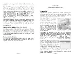
Two paralleled coaxial power connect-
ers allow ‘daisy-chaining’ INOmini mod-
ules. This allows one DC supply to
power up to three modules mounted in
a single rack adapter, provided that the
rating of the supply is not exceeded.
Two short ‘pigtail’ cables are provided
with each rack adapter.
The INOmini 661 draws 335mA. Check
the rating on the label of the power
supply to make sure it has sufficient
capacity for all modules it must sup-
port.
These power connectors are not a lock-
ing type, and the mating plugs pull out
rather easily. A Ty-Wrap® can secure
the cables to the plastic anchor above
the jacks.
— 10 —
Section III
OPERATING THE INOmini 661
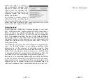
Hey, why is the screen flashing?
The INOmini 661 activates alarms for various reception
problems, which are detailed later in this section. But you
may encounter an alarm shortly after you power-up the
unit. These alarms identify the condition, flashing their
warning against a red background, quite visible even across
the room.
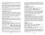
If you have not yet set-
up the unit for use, one
or more of the
DAB
LOSS
,
LOW SIGNAL
and
AUDIO LOSS
alarms may
begin to flash soon after the receiver is powered up. If you
push or turn the knob, you will get a few seconds’ breather
from the flashing, enough time to navigate to any of the
setup menus. Of course, once a station has been tuned-in
properly the alarm condition will be reset.
Whenever you are in the ‘edit mode’; that is, you have en-
tered a menu to edit (make a change to) a setup item, the
front-panel flashing alarm is inhibited while that parameter
is being programmed. The edit mode times out after 30
seconds if no change is made.
The rear-panel tally outputs will always be active for the du-
ration of an alarm, even when front-panel flashing pauses
temporarily.
NOTE:
Do not confuse flashing alarms with ‘blinking’ menu
callouts, which indicate options for editing.
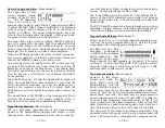
Menu Navigation Basics
By the time you’ve read this, you’ve probably already fig-
ured out the INOmini 661 menu for yourself, as intuitive as
it is. Quite simply: 1)
turn
the knob to navigate from one
menu to the next, 2)
push
the knob to enter any menu asso-
ciated with setup, 3)
turn
the knob to make a selection or to


