
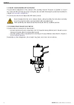
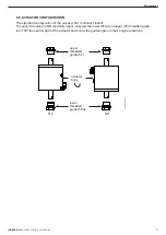
To perform the air connection to the actuator:
-
connect and check the air connections (G 1/8’’ thread for tubing Ø6 mm)
with thread in accor-
dance with double-effect or simple effect needs.
-
mind the quality of the compressed air according to the specifications described in chapter
9.
Technical Specifications
.
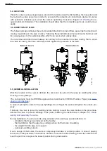
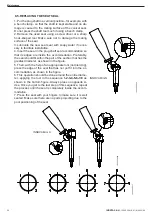
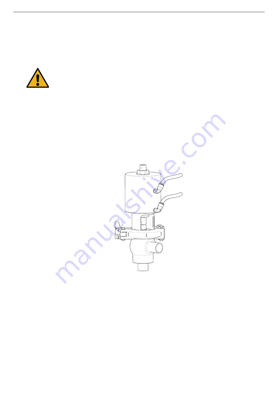
5.9. VALVE CONFIGURATION WITH ACTUATOR
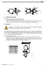
5.10. CONNECTING THE AIR TO ACTUATOR
The standard configuration of the valves is NC (normally closed). However, is possible to convert
the valve into NO (normally open) by turning the valve actuator following the procedure described in
chapter
8.6. Actuator configuration
.
The valves can also be configured as DE valves (air-air).
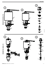
Never disassemble the valve clamps directly without reading the instructions carefully
since the actuator contain a spring inside it with an applied load.
Valve assembly and disassembly should only be done by qualified persons.
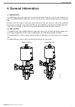
Depending on the configuration, the actuator may have one or two air connections.
10.260.32.0035
Installation
INOXPA S.A.U.
10.260.30.01EN · (A) 2022/09
12


