background image

1. Table of Contents

1. 

Table of Contents

2. Generalities

2.1. Instructions  manual .................................................................................................................................6
2.2. Compliance with the instructions ............................................................................................................6
2.3. Warranty..................................................................................................................................................6

3. Safety

3.1. Warning  symbols.....................................................................................................................................7
3.2. General safety instructions .....................................................................................................................7

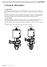
4. General  Information

4.1. Description ..............................................................................................................................................9
4.2. Application ...............................................................................................................................................9

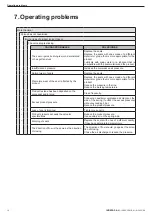
5. Installation

5.1. Reception of the valve ..........................................................................................................................10
5.2. Transport and storage ...........................................................................................................................10

5.3. Identification of the valve

 ......................................................................................................................10

5.4. Location ................................................................................................................................................12

5.6. Direction of flow

 ....................................................................................................................................12

5.5. General  installation ...............................................................................................................................12
5.7. Checking and review .............................................................................................................................13
5.8. Welding .................................................................................................................................................13

5.9. Valve configuration with actuator

 ..........................................................................................................14

5.10. Connecting the air to actuator .............................................................................................................14

6. Start-up

7. Operating  problems

8. Maintenance

8.1. General  considerations .........................................................................................................................17
8.2. Maintenance .........................................................................................................................................17
8.3. Cleaning ................................................................................................................................................18
8.4. Disassembly and assembly the valve ...................................................................................................20
8.5. Replacing the seat seal .........................................................................................................................22

8.6. Actuator configuration

 ...........................................................................................................................23

9. Technical Specifications

9.1. Valve
9.2. Actuator .................................................................................................................................................24
9.3. Materials ...............................................................................................................................................24
9.4. Sizes  available ......................................................................................................................................24
9.5. Weights of the INNOVA Mini N and INNOVA Mini K valve  ...................................................................25
9.6. Dimensions of the INNOVA Mini N and INNOVA Mini K valve ..............................................................25
9.7. Exploded drawing and parts list of the INNOVA Mini N valve ...............................................................26
9.8. Exploded drawing and parts list of the INNOVA Mini K valve ...............................................................27

Summary of Contents for Aseptic INNOVA Mini K

Page 1: ...SINGLE SEAT VALVE INNOVA Mini N K Original Instructions 10 260 30 01EN A 2022 09 INSTALLATION SERVICE AND MAINTENANCE INSTRUCTIONS 10 260 32 0002 10 260 32 0003 ...

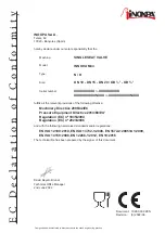
Page 2: ...of the following directive Machinery Directive 2006 42 EC Pressure Equipment Directive 2014 68 EU1 Regulation EC nº 1935 2004 Regulation EC nº 2023 2006 and with the following harmonized standards and or regulations EN ISO 12100 2010 EN ISO 13732 1 2008 EN 1672 2 2005 A1 2009 EN ISO 14159 2008 EN 12266 1 2012 EN 19 2016 The technical file has been prepared by the signer of this document Size DN 10...

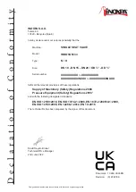
Page 3: ... all the relevant provisions of these regulations and with the following designated standards EN ISO 12100 2010 EN ISO 13732 1 2008 EN 1672 2 2005 A1 2009 EN ISO 14159 2008 EN 12266 1 2012 EN 19 2016 The technical file has been prepared by the signer of this document Size DN 10 DN 15 DN 20 OD OD IXXXXXXXXX to IXXXXXXXXX XXXXXXXXXIINXXX to XXXXXXXXXIINXXX Supply of Machinery Safety Regulations 2008...

Page 4: ... 13 5 8 Welding 13 5 9 Valve configuration with actuator 14 5 10 Connecting the air to actuator 14 6 Start up 7 Operating problems 8 Maintenance 8 1 General considerations 17 8 2 Maintenance 17 8 3 Cleaning 18 8 4 Disassembly and assembly the valve 20 8 5 Replacing the seat seal 22 8 6 Actuator configuration 23 9 Technical Specifications 9 1 Valve 9 2 Actuator 24 9 3 Materials 24 9 4 Sizes availab...

Page 5: ...ight to claim damages This non compliance may cause the following risks failure of important machine plant functions failure of specific maintenance and repair procedures possible electrical mechanical and chemical hazards risk to the environment due to the type of substances released 2 3 WARRANTY The conditions of the warranty are specified in the General Sales Condition that has been delivered a...

Page 6: ...ration Always take into account the Technical Specifications of chapter 9 NEVER exceed the specified limit values NEVER touch the valve and or piping that is in contact with the fluid during operation If the process involves hot products there is a risk of burns The valve contains parts that move in a linear fashion Do not place hands or fingers in the valve closing area This can cause serious inj...

Page 7: ...ncompatible products since if there is a failure in the union if may not be detected and the products could mix 4 1 DESCRIPTION 4 2 APPLICATION The INNOVA Mini N and INNOVA Mini K single seat valve are a sanitary and flexible design for a wide range of applications in the food pharmaceutical chemical and beverage industries The INNOVA Mini N valve is usually used for emptying drainage or as a shut...

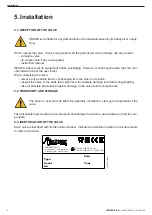
Page 8: ...he parts that comprise it for possible damage incurred during shipping take all possible precautions against damage to the valve and its components 5 2 TRANSPORT AND STORAGE The buyer or user shall be liable for assembly installation start up and operation of the valve Take all possible precautions when transport and storage the valve to avoid damage it and its com ponents 5 3 IDENTIFICATION OF TH...

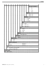
Page 9: ...E NO Size 010 DN 10 015 DN 15 OD 020 DN 20 OD Seals 43 HNBR 52 EPDM 78 FPM Material 06 1 4404 AISI 316L Connection 0 Welded Standard pipe 0 DIN 1 OD Bodies configuration L T INNOVA N H E F G INNOVA K Type N shut off valve reverse acting K routing converging flow Product family WA INNOVA valve Installation 9 INOXPA S A U 10 260 30 01EN A 2022 09 ...

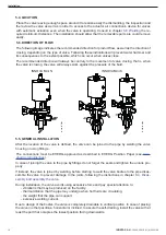
Page 10: ...y special attention to vibrations that may be produced on the facility thermal dilation that the pipe may undergo when hot fluids are circulating the weight that the pipe can support excessive welding current The connections must be EHEDG approved as described in EHEDG Position Paper see www ehedg org guidelines 5 6 DIRECTION OF FLOW The following image indicates the recommended direction for prod...

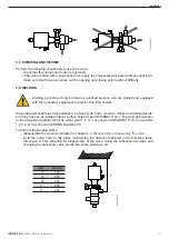
Page 11: ...olds crevices cracks and misalignments and may have an as welded interior surface finish as per AWS ANSI D 18 1 The weld discoloration in the as welded condition shall be either weld 1 2 or 3 as shown in AWS ANSI D 18 2 or weld No 1 2 3 4 or 5 as shown in EHEDG Guideline 35 To perform the welding works disassemble the valve as indicated in chapter 8 4 Disassembly and assembly the valve weld the va...

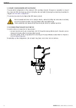
Page 12: ... is NC normally closed However is possible to convert the valve into NO normally open by turning the valve actuator following the procedure described in chapter 8 6 Actuator configuration The valves can also be configured as DE valves air air Never disassemble the valve clamps directly without reading the instructions carefully since the actuator contain a spring inside it with an applied load Val...

Page 13: ...ompressed air pressure at the inlet of the actuator matches what is indicated in chapter 9 Technical Specifications consider the quality of the compressed air according to the specifications described in chapter 9 Technical Specifications activate the valve Before start up the persons in charge must be duly informed about how the valve works and the safety instructions to follow This instruction m...

Page 14: ... that is more appropriate for the product Reduce the pressure in the line Reduce the working temperature Product residue has been deposited on the valve seat and or plug Clean frequently Excess product pressure Connect an auxiliary compressed air nipple on the side of the spring to offset the excess pressure without exceeding 4 bar Reduce the product pressure Loss of seal vibrations Tighten loose ...

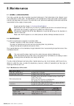
Page 15: ...ement seals in stock Pay special attention to the hazard warnings indicated in this manual during the performance of the maintenance work The valve and the pipes must never be under pressure during maintenance Burn hazard Do not touch the valve or the pipes when hot fluids are circulating or when cleaning and or sterilization are being carried out 8 2 1 Maintenance of the seals REPLACING SEAL Prev...

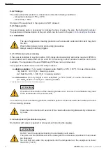
Page 16: ...e valve is installed in a system with a CIP process its disassembly will not be required EPDM is the standard seal material that will be used for CIP cleaning both in alkaline mediums and in acid mediums The materials of the seal HNBR and FPM are not recommended Two types of solutions can be used for CIP processes a alkaline solution 1 by weight of caustic soda NaOH a 70ºC 150ºF To make this solut...

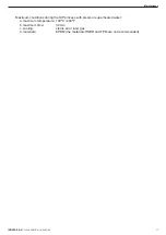
Page 17: ...s with steam or superheated water a maximum temperature 140ºC 284ºF b maximum time 30 min c cooling sterile air or inter gas d materials EPDM the materials HNBR and FPM are not recommended Maintenance 17 INOXPA S A U 10 260 30 01EN A 2022 09 ...

Page 18: ... 9 Unscrew and remove the lower threaded gui de 55A from the actuator 10 10 Separate the lantern 21 11 Remove the conical seat seal 05C from the plug shaft 08 following the instructions in chap ter 8 5 Replacing the seat seal 12 At the INNOVA Mini K valves remove the ra dial seat seal 05D following the instructions in chapter 8 5 Replacing the seat seal 1 Lubricate the seals with soapy water or su...

Page 19: ...A Mini N 21 01 55A 55 10 17 08 21 05C 05 20B 12 55A 1 2 3 05C 05D 08 05 17 20B 12 55A 21 10 260 32 0011 34 08 21 01 10 01 55A 21 10 55 1 2 3 INNOVA Mini K 10 260 32 0010 Maintenance 19 INOXPA S A U 10 260 30 01EN A 2022 09 ...

Page 20: ...in the part of the section that has the greatest diameter as shown in the figure 5 Then with the help of an appropriate tool not piercing press the edge of the seal that has not yet fit into the ac commodation as shown in the figure 6 This operation should be done around the entire diame ter applying the tool in the sequence 1 2 3 4 5 6 7 8 as shown in the bottom figure Always press on opposite si...

Page 21: ...alve to NO normally open unscrew the lower 55A and upper 55 threaded guide turn 180 the central part of the actuator and screw the guides again in their original positions 10 260 32 0013 lower threaded guide 55A upper threaded guide 55 actuator body NC NO Maintenance 21 INOXPA S A U 10 260 30 01EN A 2022 09 ...

Page 22: ...ure conditions the dew point must be adjus ted accordingly Oil content quality class 5 preferentially oil free max 25 mg oil per 1m3 air Compressed air fitting G 1 8 Compressed air consumption litres N cycle of Prel 6 bar DIN EN 10357 serie A DN 10 DN 15 DN 20 formerly DIN 11850 series 2 ASTM A269 270 OD OD correspond to tubo OD Connections Weld DN SE air spring DE air air DIN 10 0 2 1 1 15 0 2 1 ...

Page 23: ...2 0 2 3 2 0 2 4 A B DN DN Dimensions mm A B DIN 10 120 207 15 120 207 20 120 207 OD 120 207 120 207 9 6 DIMENSIONS of the INNOVA Mini N and INNOVA Mini K VALVE 10 260 32 0014 A B DN 10 260 32 0015 DN Dimensions mm A B DIN 10 120 247 15 120 247 20 120 247 OD 120 247 120 247 Technical Specifications 23 INOXPA S A U 10 260 30 01EN A 2022 09 ...

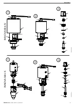
Page 24: ...1 1 4404 AISI 316L 10 actuator 1 1 4307 AISI 304L 12 body cover 1 1 4404 AISI 316L 17 upper guide bushing 1 PTFE 20B O ring1 1 EPDM FPM HNBR 21 lantern 1 1 4307 AISI 304L 34 clamp 1 1 4301 AISI 304 55 upper threaded guide 1 PTFE 55A lower threaded guide 1 PTFE 1 recommended spare parts 05 05C 17 08 21 34 01 20B 12 55A 55 10 10 260 32 0016 Technical Specifications INOXPA S A U 10 260 30 01EN A 2022...

Page 25: ...I 316L 05 shaft seal1 1 EPDM 05C conical seat seal1 1 EPDM FPM HNBR 05D radial seat seal1 1 EPDM FPM HNBR 08 plug shaft 1 1 4404 AISI 316L 10 actuator 1 1 4307 AISI 304L 12 body cover 1 1 4404 AISI 316L 17 upper guide bushing 1 PTFE 20B O ring1 1 EPDM FPM HNBR 1 recommended spare parts 10 260 32 0017 Technical Specifications 25 INOXPA S A U 10 260 30 01EN A 2022 09 ...

Page 26: ...scription Quantity Material 21 lantern 1 1 4307 AISI 304L 34 clamp 1 1 4301 AISI 304 55 upper threaded guide 1 PTFE 55A lower threaded guide 1 PTFE Technical Specifications INOXPA S A U 10 260 30 01EN A 2022 09 26 ...

Page 27: ...___________________________________________________________________ ________________________________________________________________________ ________________________________________________________________________ ________________________________________________________________________ ________________________________________________________________________ ________________________________________...

Page 28: ...act INOXPA S A U Contact details for all countries are continaually updated on our website Please visit www inoxpa com to access the information INOXPA S A U Telers 60 17820 Banyoles Spain 10 260 30 01EN A 2022 09 ...

Reviews: