background image

6

DRAIN LINE CONNECTIONS

DRAIN LINE CONNECTIONS

DRAIN LINE CONNECTIONS

DRAIN LINE CONNECTIONS

DRAIN LINE CONNECTIONS

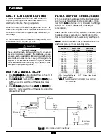
To allow easy access to overload reset button, the

disposer plumbing should be connected with the

electrical control box facing the operator.

When connecting the drain line, place the “P-trap” as

close to the disposer outlet flange as possible.  Do not

connect the drain line to a grease trap, interceptor, or

drum trap.

All horizontal runs should be as short as possible, with

a minimum fall of 1/4 inch per foot.

ROUTING WATER FLOW

ROUTING WATER FLOW

ROUTING WATER FLOW

ROUTING WATER FLOW

ROUTING WATER FLOW

• In a trough system

trough system

trough system

trough system

trough system, route all water flow to the end of

the trough to flush food waste.

• In an sink bowl

sink bowl

sink bowl

sink bowl

sink bowl system with an SS-50 

SS-50 

SS-50 

SS-50 

SS-50 to SS-125

 SS-125

 SS-125

 SS-125

 SS-125 (3-5

GPM), , , , , route all water through the sink bowl (see

Table 2).

• In a sink bowl

sink bowl

sink bowl

sink bowl

sink bowl system with an SS-150 

SS-150 

SS-150 

SS-150 

SS-150 to SS-1000

SS-1000

SS-1000

SS-1000

SS-1000 (7-

10 GPM), route water through the sink bowl 

and the

disposer body inlet.

PLUMBING

PLUMBING

PLUMBING

PLUMBING

PLUMBING

Property Damage

These plumbing instructions were written for an experi-
enced and competent installer. If the installer is not expe-
rienced in plumbing installation, ISE recommends that com-
petent professional assistance is sought.  Damage to the
disposer or accessories as a result of improper installa-
tion is not covered under warranty.  All installations must
comply with local plumbing codes.

DRAIN LINE CONNECTIONS

DRAIN LINE CONNECTIONS

DRAIN LINE CONNECTIONS

DRAIN LINE CONNECTIONS

DRAIN LINE CONNECTIONS

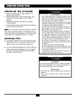
Figure 9:  

Figure 9:  

Figure 9:  

Figure 9:  

Figure 9:  

Water & Electrical Connections

F

LOW

C

ONTROL

V

ALVE

W

ATER

S

OLENOID

V

ALVE

W

ATER

S

UPPLY

D

ISPOSER

S

INK

W

ATER

 I

NLET

C

ONNECTION

(

OPTIONAL

)

1/2 NPT

S

IPHON

B

REAKER

S

TART

/S

TOP

S

WITCH

E

LECTRICAL

S

UPPLY

WATER SUPPLY CONNECTIONS

WATER SUPPLY CONNECTIONS

WATER SUPPLY CONNECTIONS

WATER SUPPLY CONNECTIONS

WATER SUPPLY CONNECTIONS

When connecting the disposer to the incoming water

supply, use as few elbows and tees as possible.  (Con-

nect to the cold

cold

cold

cold

cold water line only.)  All water line fittings

are 1/2” NPT except the sink bowl nozzles (1/2”

compression).

Install the flow control valve, water solenoid valve, and

the siphon breaker according to the direction of the

flow arrows marked on each valve body (see Figure 9).

NOTE:

NOTE:

NOTE:

NOTE:

NOTE:  A siphon breaker must be installed above the

sink flood plane per local plumbing codes.

Disposer

Water Flow

Drain Line

GPM (LPM)

Diameter

SS-50

3 (11)

1 1/2"

SS-75

3 (11)

1 1/2"

SS-100

5 (19)

1 1/2"

SS-125

5 (19)

1 1/2"

SS-150

7 (26)

2" NPT

SS-200

7 (26)

2" NPT

SS-300

8 (30)

3" NPT

SS-500

8 (30)

3" NPT

SS-750

10 (38)

3" NPT

SS-1000

10 (38)

3" NPT

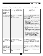
GPM = Gallons Per Minute         NPT = National Pipe Thread

LPM = Liters Per Minute

Table 2:  

Table 2:  

Table 2:  

Table 2:  

Table 2:  

Recommended Cold Water Flow & Drain

Line Diameter

Summary of Contents for 13954

Page 1: ......

Page 2: ...tallation The warranty in cludes parts and labor provided the service is performed by an In Sink Erator Factory Authorized Service Center This warranty does not apply if failure is due to faulty or im...

Page 3: ...g Plumbing 6 Drain Line Connections 6 Routing Water Flow 6 Water Supply Connections 6 Electrical Electrical Electrical Electrical Electrical 7 Electrical Safety 7 Electrical Connections 7 Disposer Con...

Page 4: ...r Factory Authorized Service Centers do not make original installations For technical information not covered in these instructions contact the supplier an In Sink Erator Field Sales Representa tive o...

Page 5: ...rated in Figure 2 Moving shredder parts may cause serious injury if a hopper or cone is not properly installed A A A A A A A A A A The minimum required distance from the table top or trough to the mou...

Page 6: ...the sink and the strainer flange is held securely in place 5 Place the body flange 9 9 9 9 9 lugs upward over the lip of the mounting flange 10 10 10 10 10 and fit the mounting gasket 8 8 8 8 8 onto t...

Page 7: ...e gasket is fully seated on the flange 3 Push the mounting flange down over the mounting gasket fitting the threaded mounting flange fasten ers into the recesses in the top of the mounting gasket 4 Fr...

Page 8: ...commends that com petent professional assistance is sought Damage to the disposer or accessories as a result of improper installa tion is not covered under warranty All installations must comply with...

Page 9: ...ally Make sure the disposer is securely mounted and does not leak from any of the connections ELECTRICAL SAFETY ELECTRICAL SAFETY ELECTRICAL SAFETY ELECTRICAL SAFETY ELECTRICAL SAFETY ELECTRICAL ELECT...

Page 10: ...sonal injury and or disposer damage To reduce the risk of injury from materials that may be expelled from the disposer grind chamber ensure that the disposer baffle is properly installed To prevent th...

Page 11: ...nd forth to free the jam The rotating shredder should revolve freely when the jam is re leased 3 Remove all foreign material that caused the stoppage 4 Allow the disposer to cool for 3 5 minutes after...

Page 12: ...ES NOTES NOTES All electrical connections must comply with local electrical codes Pressure switches may be connected across the line at 5 horsepower or less Larger horsepower motors require connection...

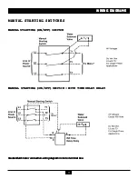
Page 13: ...OFF SWITCH WITH TIME DELAY RELAY MANUAL STARTING ON OFF SWITCH WITH TIME DELAY RELAY MANUAL STARTING ON OFF SWITCH WITH TIME DELAY RELAY MANUAL STARTING ON OFF SWITCH WITH TIME DELAY RELAY MANUAL STA...

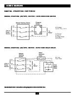
Page 14: ...N OFF SWITCH WITH PRESSURE SWITCH MANUAL STARTING ON OFF SWITCH WITH TIME DELAY RELAY MANUAL STARTING ON OFF SWITCH WITH TIME DELAY RELAY MANUAL STARTING ON OFF SWITCH WITH TIME DELAY RELAY MANUAL STA...

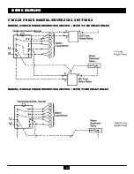
Page 15: ...RSING SWITCHES SINGLE PHASE MANUAL REVERSING SWITCHES MANUAL SINGLE PHASE REVERSING SWITCH MANUAL SINGLE PHASE REVERSING SWITCH MANUAL SINGLE PHASE REVERSING SWITCH MANUAL SINGLE PHASE REVERSING SWITC...

Page 16: ...Y MANUAL SINGLE PHASE REVERSING SWITCH WITH TI ME DELAY RELAY MANUAL SINGLE PHASE REVERSING SWITCH WITH TI ME DELAY RELAY MANUAL SINGLE PHASE REVERSING SWITCH WITH TI ME DELAY RELAY MANUAL SINGLE PHAS...

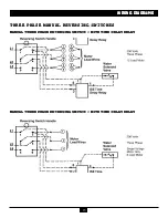
Page 17: ...ELAY MANUAL THREE PHASE REVERSING SWITCH WITH TIME DELAY RELAY MANUAL THREE PHASE REVERSING SWITCH WITH TIME DELAY RELAY MANUAL THREE PHASE REVERSING SWITCH WITH TIME DELAY RELAY MANUAL THREE PHASE RE...

Page 18: ...THREE PHASE REVERSING SWITCH MANUAL THREE PHASE REVERSING SWITCH MANUAL THREE PHASE REVERSING SWITCH MANUAL THREE PHASE REVERSING SWITCH WITH TIME DELAY RELAY MANUAL THREE PHASE REVERSING SWITCH WITH...

Page 19: ...EE PHASE REVERSING SWITCH STANDARD MOTOR CONNECTION WIRING DIAGRAMS STANDARD MOTOR CONNECTION WIRING DIAGRAMS STANDARD MOTOR CONNECTION WIRING DIAGRAMS STANDARD MOTOR CONNECTION WIRING DIAGRAMS STANDA...

Page 20: ...13954 October 13954 October 13954 October 13954 October 1997 1997 1997 1997 1997 http www http www http www http www http www ser ser ser ser service insink vice insink vice insink vice insink vice i...

Reviews: