background image

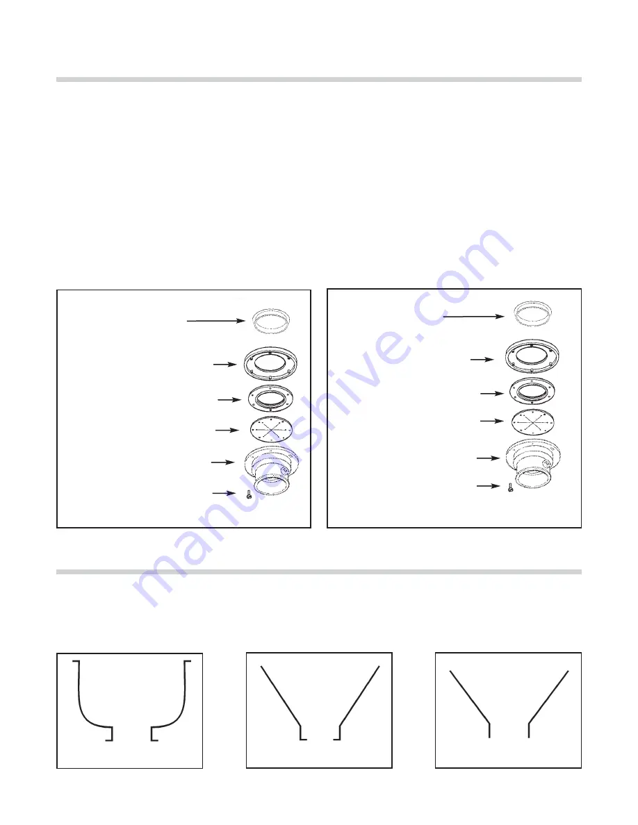
1. Place the mounting flange (1) over the existing collar

adaptor connection lip or sink bowl flange (this may
require some force). 

2. Push the mounting flange up out of the way and fit the

groove in the mounting gasket (2) onto the connection
lip.  Make sure the gasket is fully seated on the flange.

3. Push the mounting flange down over the mounting gasket,

fitting the threaded mounting flange fasteners into the
recesses in the top of the mounting gasket.

Special In-Sink-Erator Mountings

4. From the bottom, insert two screws through opposite

sides of the flat gasket (3) and mounting flange, into the
threaded fasteners in the existing flange.  The flat gasket
is used only in the #6 mounting assembly.  The screws
should protrude about 1/4 inch below the mounting 
gasket.

5. Position the disposer beneath the mounting gasket and

raise it to engage the two protruding screws in the dis-
poser body flange keyhole slots.  Secure the remaining
screws and position the disposer correctly for the plumb-
ing connections.  For 3-10 H.P. disposers, adjust the legs
to support the disposer.

When installing an In-Sink-Erator commercial disposer to a non-In-Sink-Erator style sink bowl, a special mounting adaptor kit
is required. The special mountings are described in the Mounting Adaptor Selection Guide (for more information, call 1-800
558-5712). Figures 6-8 show examples of non-In-Sink-Erator style sinks. (Mounting instructions are included in each special
mounting adaptor kit.)

Figure 7: Inward Flange

Figure 8: Straight Flange

Figure 6: Outward Flange

#6, #7, & SINK BOWL MOUNTING ASSEMBLIES

Figure 4: #6 Mounting Assembly

Figure 5: #7  or Sink Bowl Mounting Assembly

Standard In-Sink-Erator Mountings

#6 Collar Adaptor

(1) Mounting Flange

(2) Mounting Flange

(3) Flat Gasket

Disposer Body Flange

1/4" Screw

#7 Collar Adaptor

Sink Bowl

(1) Mounting Flange

(2) Mounting Gasket

1/4" Screw

Disposer Body Flange

5

Summary of Contents for Model SS-100

Page 1: ...ANGER DANGER indicates an imminently hazardous situation which if not avoided will result in death or serious injury WARNING indicates a potential hazardous situation which if not avoided could result...

Page 2: ...d unit as specified by In Sink Erator Commercial disposer accessories are included in this warranty only if they are included in the original disposer purchase package Introduction 2 Typical Installat...

Page 3: ...Wisconsin at 1 800 558 5712 CST 7 30 am 4 30 pm CLEAN THE DRAIN LINE With a drain line auger clear away all hardened waste material in the horizontal drain pipe running from the drain trap to the main...

Page 4: ...body disposers as specified by UL see Figure 2 In Sink Erator recommends a minimum countertop thick ness of 16 gage stainless steel Mounting Adaptors There are two adaptor categories for mounting In...

Page 5: ...e mounting flange 10 and fit the mounting gasket 8 onto the lip 6 Place the mounting gasket 11 on the disposer body flange Secure the mounting flange 10 to the disposer body flange with six screws 12...

Page 6: ...ngage the two protruding screws in the dis poser body flange keyhole slots Secure the remaining screws and position the disposer correctly for the plumb ing connections For 3 10 H P disposers adjust t...

Page 7: ...aste Xpress is wired for 460v or 208 230v The wiring information for each is shown in Figure 11 6 Property Damage These plumbing instructions were written for an experi enced competent installer If th...

Page 8: ...ource Personal Injury Property Damage If the electrical installer is not experienced in electrical installation we recommend seeking competent professional assistance Disposer or accessory damage due...

Page 9: ...could cause personal injury and or disposer damage To reduce the risk of injury from materials that may be expelled from the disposer grind chamber ensure that the disposer baffle is properly install...

Page 10: ...e disposer remains inoperative after following these steps contact the nearest In Sink Erator Factory Authorized Service Center You may obtain the telephone number of the Service Center nearest you by...

Page 11: ...rs A time delay may only be used with a water solenoid valve Start Switch Start Switch Property Damage Ensure that the control center voltage and phase match the disposer motor and electrical supply C...

Page 12: ...l local electrical codes All control centers and disposers must be carefully and permanently grounded A properly fused disconnect must be installed at the electri cal supply source for the control cen...

Page 13: ...er before attempt ing any work on it Use a voltmeter or circuit tester to ensure power is off Installation must conform to all local electrical codes All control centers and disposers must be carefull...

Page 14: ...k Turn off all electrical supply to the disposer before attempt ing any work on it Use a voltmeter or circuit tester to ensure power is off Installation must conform to all local electrical codes All...

Page 15: ...sposer before attempt ing any work on it Use a voltmeter or circuit tester to ensure power is off Installation must conform to all local electrical codes All control centers and disposers must be care...

Page 16: ...o the disposer before attempt ing any work on it Use a voltmeter or circuit tester to ensure power is off Installation must conform to all local electrical codes All control centers and disposers must...

Page 17: ...codes All control centers and disposers must be carefully and permanently grounded A properly fused disconnect must be installed at the electri cal supply source for the control center Manual Three Ph...

Page 18: ......

Page 19: ......

Reviews: