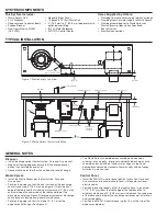
Trough Flow
Water Nozzle
Recommended
Magnet Location
Optional Magnet Location
Connect Cold Water Supply
1" min
(25.4 mm min)
1" (25.4 mm) min,
3" (76.2 mm) max
to end of Trough
PLUMBING NOTES
Fresh Water Connections
• 1/2" (12.7 mm) NPT – used on syphon breaker, solenoid and
flow control valve.
• 1/2" (12.7 mm) NOM compression – used on sink bowl nozzles.
• 1/2" (12.7 mm) Ridged Copper (compression) – used on hot
water connection to pulper.
• If fresh water supply is greater than 50 psi (144.7 kPa), a
pressure regulating valve must be installed in both.
• It is recommend that ball type shutoff valves be installed
in the cold and hot water lines.
• It is recommended that the hot water connected between
solenoid valve and pulper be terminated with a union for
ease of serviceability.
Waste Connection
• 2" (50.8 mm) NPT – used between disposer, Waste Xpress
and drain
• When connecting the drain line from the disposer to the
Waste Xpress use a maximum of (4) 90° bends (45° bends
are recommended) with a 1/4" (6.4 mm) drop per foot of run
or as local codes apply.
• Floor sink or drains should be installed per local codes but
kept clear of yet accessible to pulper.
• Trough applications in excess of 10' (3.1 m) and/or systems
plumbed with a cold water supply greater than 7 GPM
(26.5 LPM) must incorporate the second drain outlet from the
pulper and be drained independently to floor sink or drain.
TROUGH APPLICATION NOTES
Magnet
• Can be mounted to trough either by tack welding to using weld
studs (see instruction sheet for weld stud pattern).
• Trough magnets should be placed within 12" (304.8 mm) of
end of trough or trough intersection with sink bowl (see Figure 4).
• Additional magnets can be used as necessary.
Construction
• The recommended maximum trough length is 10' (3.1 m).
• A silver saver should be fabricated prior to end of trough to
catch utensils and dishes.
Water Supply
• For trough lengths of 10' (3.1 m) or less place water nozzle at
end of trough.
• For trough lengths greater than 10' (3.1 m) place one
water nozzle at end of trough and one mid stream.
• Do not plumb water to disposer grind chamber.
Figure 4. Trough Typical Installation
Figure 3. Trough Typical Installation Top View


